
The structure and material properties of two pairs of helical gears in herringbone gear are the same, but due to the influence of symmetry deviation on gear mesh, the meshing stiffness of the left and right groups of helical gear pairs is different. The gear hub and shaft are considered as a whole, ignoring the connection form of hub and shaft, and the undercut of herringbone gear is considered as a rigid body, and the helical gears on the left and right sides are considered as rigid connections. The change of meshing stiffness caused by symmetry deviation will change the symmetrical distribution of axial force on both sides of the original herringbone gear, thus causing axial displacement. A dynamic analysis model of herringbone gear transmission system considering symmetry deviation is established, as shown in Figure 1.
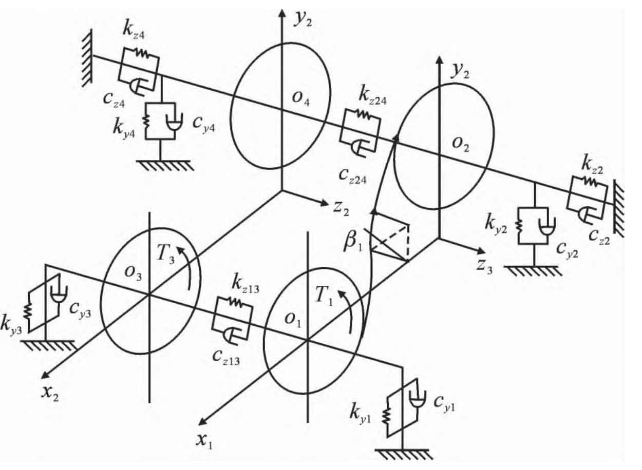
According to Newton’s second law of mechanics, the dynamic equation of the system can be obtained from Figure 1:
Where: yi, zi, θ I (i=1, 2, 3, 4) is the translation and angular displacement of the driving wheel and driven wheel center points O1, O2, O3 and O4 in z and y directions respectively; M1, m2, m3, m4, I1, I2, I3, I4 are respectively the mass and moment of inertia of the left and right helical gears of the herringbone gear; β 1 is the helix angle of herringbone gear; Fy1 and Fy2 are tangential meshing forces of helical gear pairs at left and right sides of herringbone gear; Fz1 and Fz2 are the axial meshing forces of helical gear pairs at left and right sides of herringbone gear; Rb1 and Rb2 are the radius of base circle of driving wheel and driven wheel respectively; Cy1, cy2, cy3, cy4, ky1, ky2, ky3, ky4 are the radial support damping and support stiffness of each rolling bearing; Cz2, cz4, kz2, kz4 are the axial support damping and support stiffness of the driven wheel; Cz13, cz24, kz13, kz24 are the axial tension and compression damping and stiffness of the middle undercut part of the left and right helical gears; Fs1 (t) and Fs2 (t) are the meshing impact excitation of the left and right helical gear pairs of the herringbone gear; T1 and T3 are the input torques of the driving wheels on both sides of the pinion.
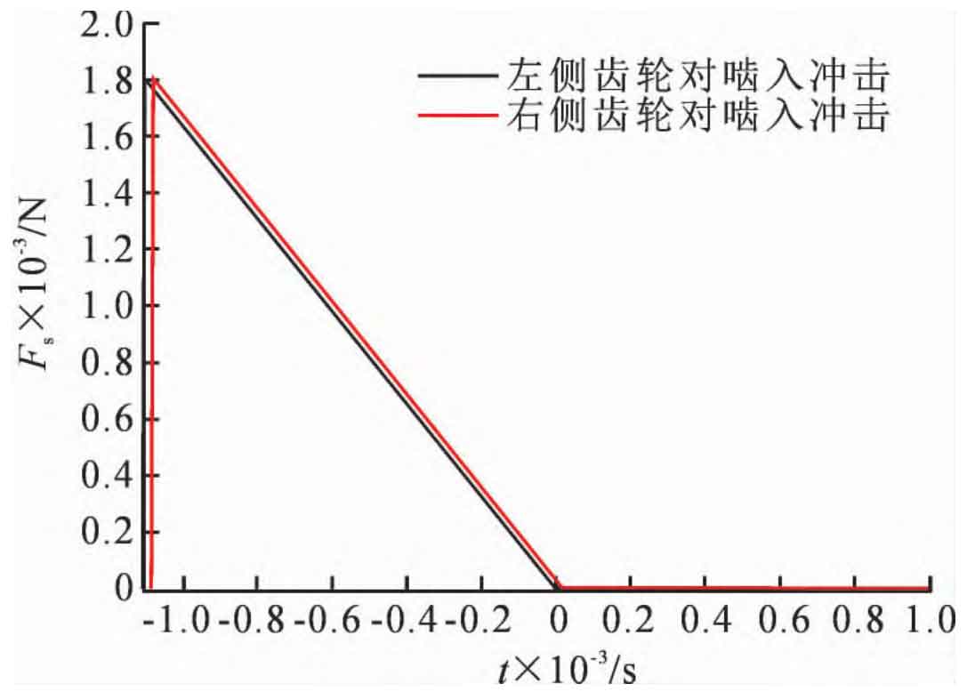
Because the meshing impact time is very short, the meshing impact force curve is usually simplified as a sawtooth wave function. From the meshing impact force curve shown in Figure 2, it can be seen that the symmetry deviation has little influence on the meshing impact on both sides of herringbone gear teeth.
The axial and radial vibration displacement and vibration velocity of the herringbone gear driving and driven wheels, as well as the torsional deformation and the change of the bearing force of the gear at the bearing can be obtained by solving the Runge Kutta method.