
1. Meshing interference inspection
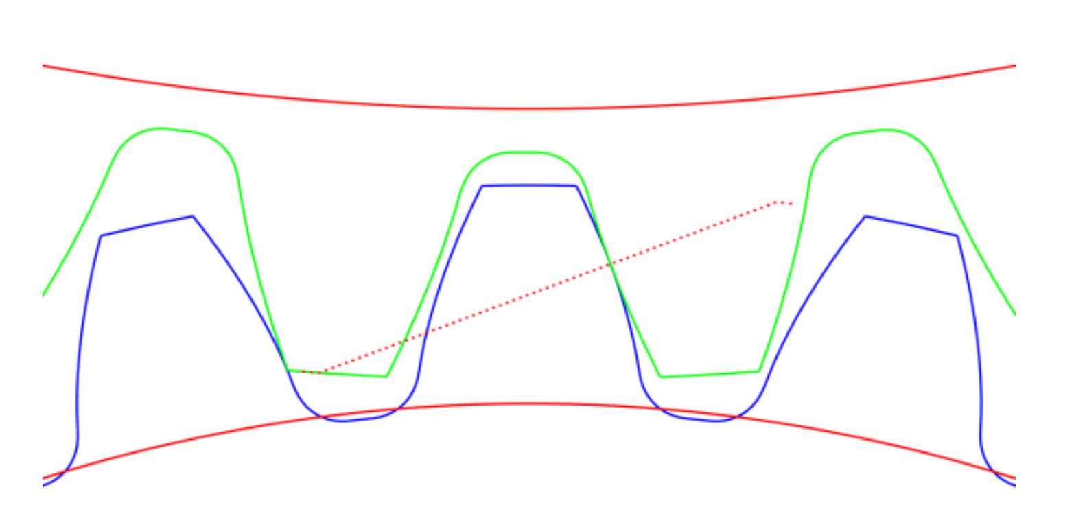
KISSsoft software can mark the contact point of the tooth surface of two gears in the meshing diagram of the helical gear pair that causes interference through the built-in “Check for meshing interference” function, thus reminding the engineer that the helical gear pair has meshing interference. Figure 3.12 shows the meshing diagram before the modification of the helical gear pair. It can be seen that one side of the two gears is exactly engaged, and there is no red dot (non red dotted line) at the contact position of the two tooth surfaces, while the other side has backlash, so the gear pair has no meshing interference.
2. Coincidence check
The total contact ratio of helical gear is equal to the sum of its end face and axial contact ratio. If its value is higher than 1, uninterrupted transmission can be achieved.
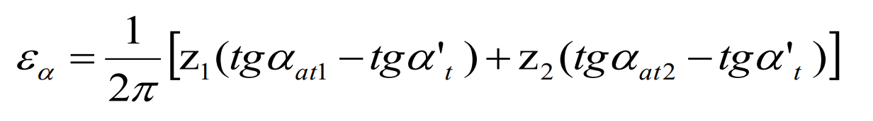
The end face coincidence can be calculated by the formula:
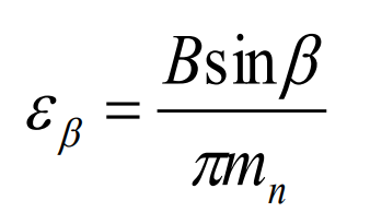
The axial coincidence can be calculated by the formula:
The total contact ratio of helical gears can be calculated by the formula:
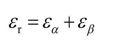
In the formula: refers to the end face coincidence, refers to the number of teeth of gear 1, refers to the number of teeth of gear 2, refers to the pressure angle of the addendum circle of gear 1, refers to the pressure angle of the addendum circle of gear 2, α T is the end face pressure angle, which is the axial coincidence, B is the tooth width, which is the helix angle, which is the normal modulus, and which is the total coincidence. It can be seen from the table that the end face and axial coincidence of helical gear pair before modification are 1.537 and 2.057 respectively. According to the formula, the total coincidence degree is 3.594, which is far greater than 1, and meets the continuous rotation meshing condition. In addition, in engineering practice, the axial coincidence ratio of helical gears for vehicles needs to be greater than 1, which is 2.057 here, fully in line.