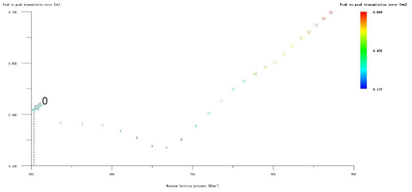
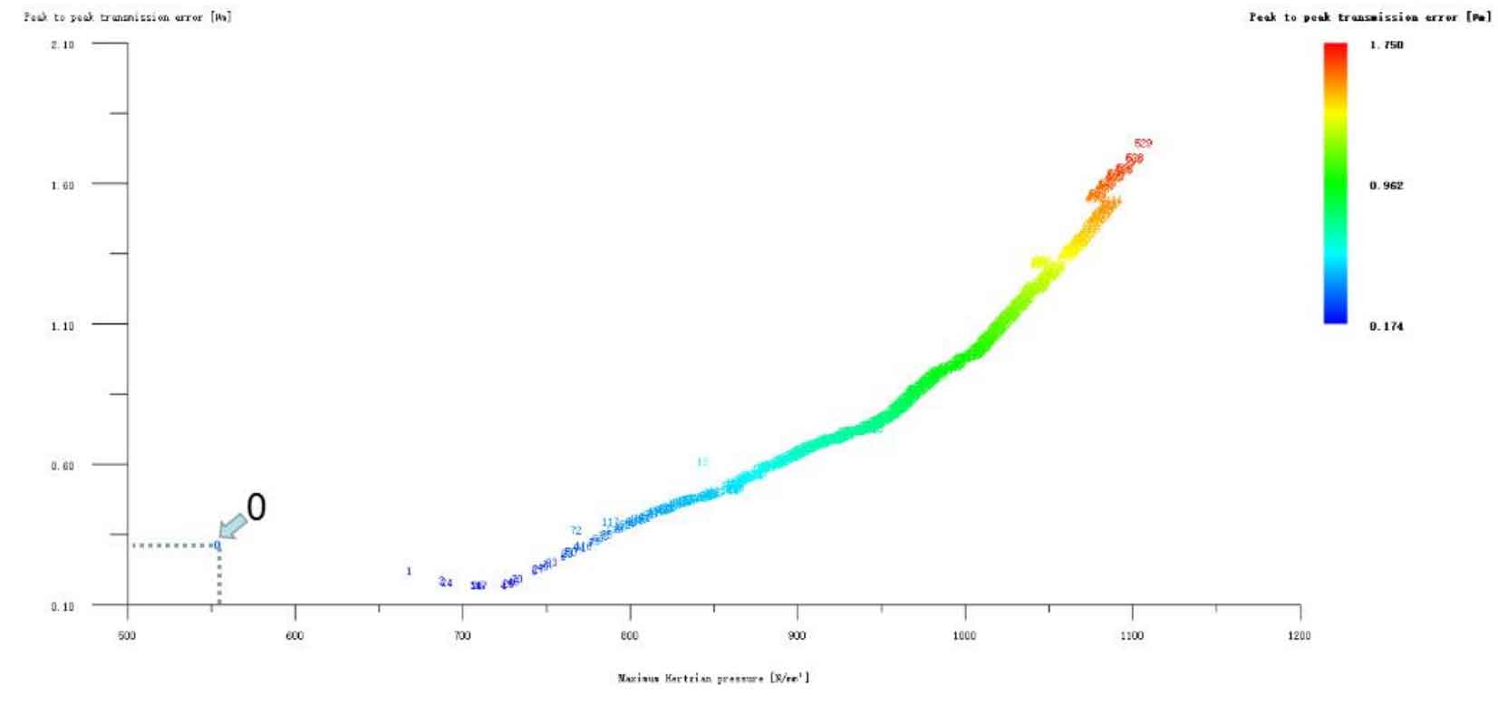
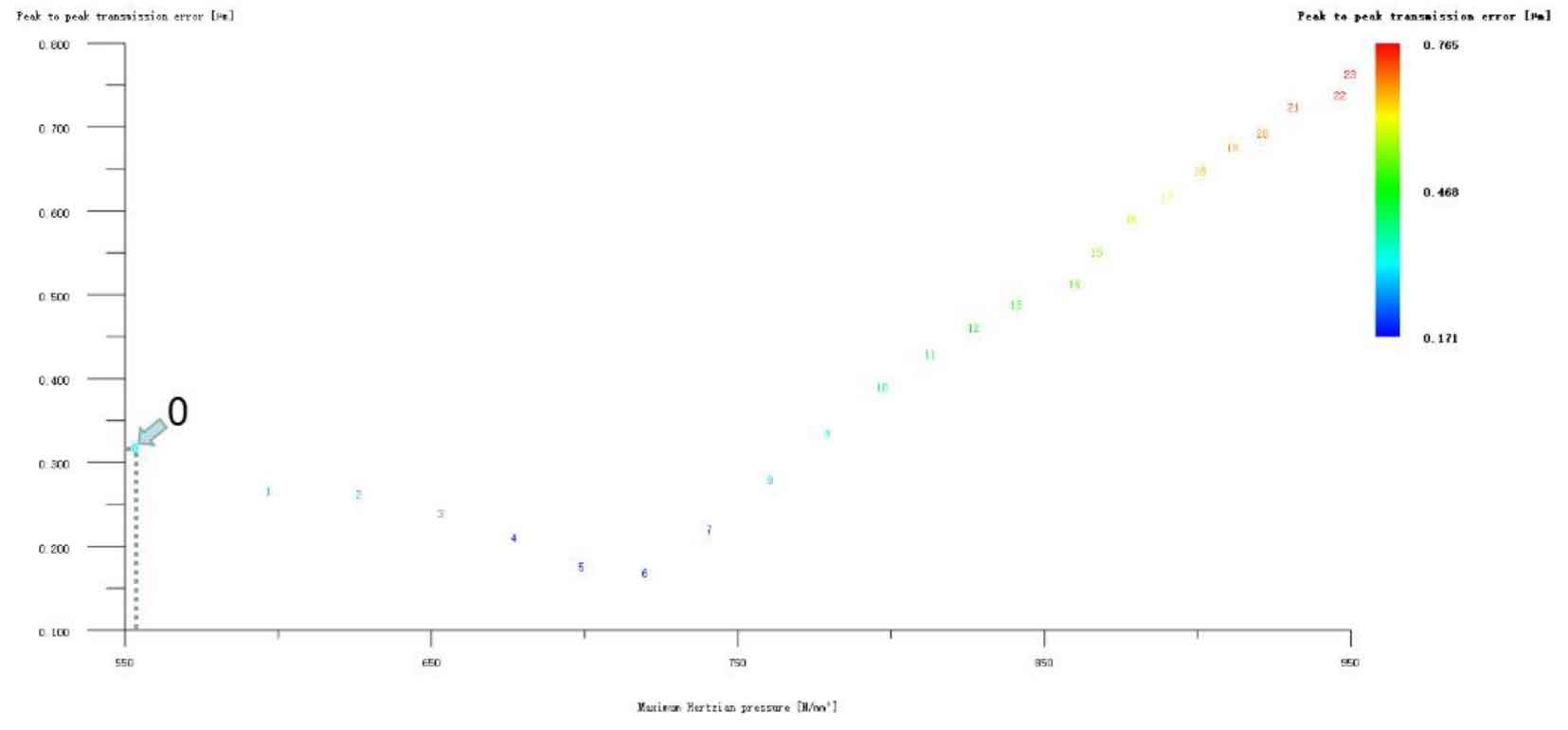
Figures 1, 2 and 3 respectively show the simultaneous tooth drum modification of wheel and pinion gears, the drum modification of pinion gears and the drum modification of wheel gears. The ordinate in all figures represents the transfer error, and the unit is μ m; The abscissa represents the Hertz contact stress, in N/mm2. It can be seen from the analysis of the three figures that although the tooth drum modification method has no special requirements on the selection of large and pinion modified helical gears, and there are all optimization schemes that reduce the transmission error of the helical gear pair, this is not consistent with the conclusion that the tooth drum modification is mainly to reduce the transmission error of the helical gear pair mentioned above, but the Hertz contact stress in these optimization schemes is relatively higher than that in the case of no modification.
It can be seen that the modification idea is based on the optimization scheme of tooth profile modification and then consider the tooth direction composite modification. If the optimization scheme of tooth direction drum modification with low transmission error reverses the tooth profile composite modification, the two schemes are repeated. Therefore, all the tooth direction drum modification schemes are omitted here.
Of course, if the engineering practice only considers vibration and noise reduction and does not care about the strength of helical gears, the tooth drum modification is the best choice. Taking helical gear pair as an example, if only the pinion tooth direction is drum shaped, the transmission error of Scheme 6 is the lowest, 0.171 μ m. Reduced by 0.148 μ m. The reduction is 46.4%, and the modification amount is pinion 6 μ m. The wheel gear is not modified.