(1) Gear profile optimization modification+tooth direction drum modification
Figures 1, 2, 3, 4 and 5 respectively show the composite modification of wheel and pinion gear tooth profile and tooth direction drum shape, the composite modification of wheel and pinion gear long tooth profile and tooth top involute plus tooth direction drum shape, the composite modification of wheel and pinion gear long tooth profile and tooth top arc plus tooth direction drum shape, the composite modification of big and small gear long tooth profile and tooth top broken arc plus tooth direction drum shape, and the composite modification of big and small gear long tooth profile and tooth top linear plus tooth direction drum shape. It can be seen from the above five figures that although there are composite optimization modification schemes that reduce the transmission error of the helical gear pair, these schemes are all at the cost of sacrificing the strength of the helical gear, that is, increasing the Hertz contact stress, so they are all rounded off.
(2) Optimized modification of tooth profile of big and small gears+drum modification of tooth direction of a helical gear
Figures 6, 7, 8, 9 and 10 respectively refer to the big and small gear tooth profile drum modification plus a helical gear tooth profile drum modification, the big and small gear long tooth profile tooth tip involute modification plus a helical gear tooth profile drum modification, the big and small gear long tooth profile tooth tip arc modification plus a gear tooth profile drum modification, the big and small gear long tooth profile tooth tip broken arc modification plus a helical gear tooth profile drum modification The long tooth profile and addendum linear modification of big and small gears plus the tooth direction drum modification of a helical gear. It can be seen from the above five figures that, except the transmission error and Hertz contact stress of the two No. 1 schemes in Fig. 9 (a) and (b) are reduced compared with the unmodified ones, the modification effect of the other schemes is generally poor. However, through in-depth analysis of the above two optimization modification schemes (as shown in Figure 11), the transmission error and Hertz contact stress increase compared with those before the composite modification, which is meaningless except for increasing the cost, so it is omitted.
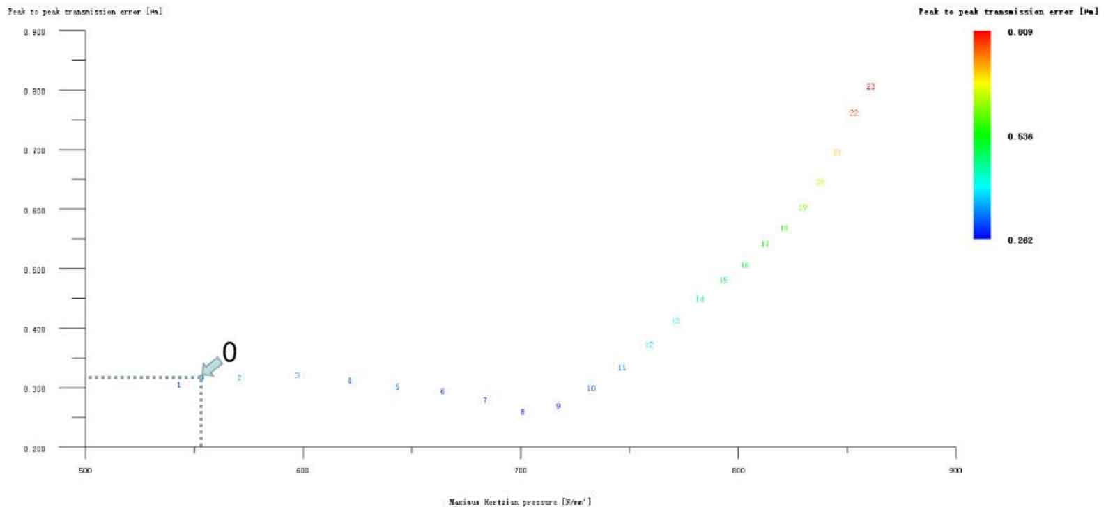
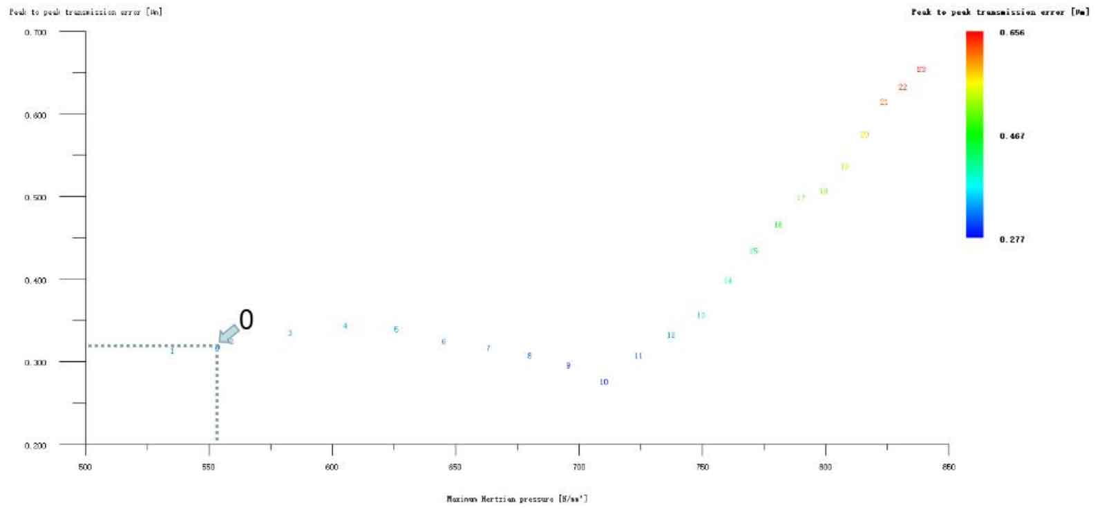

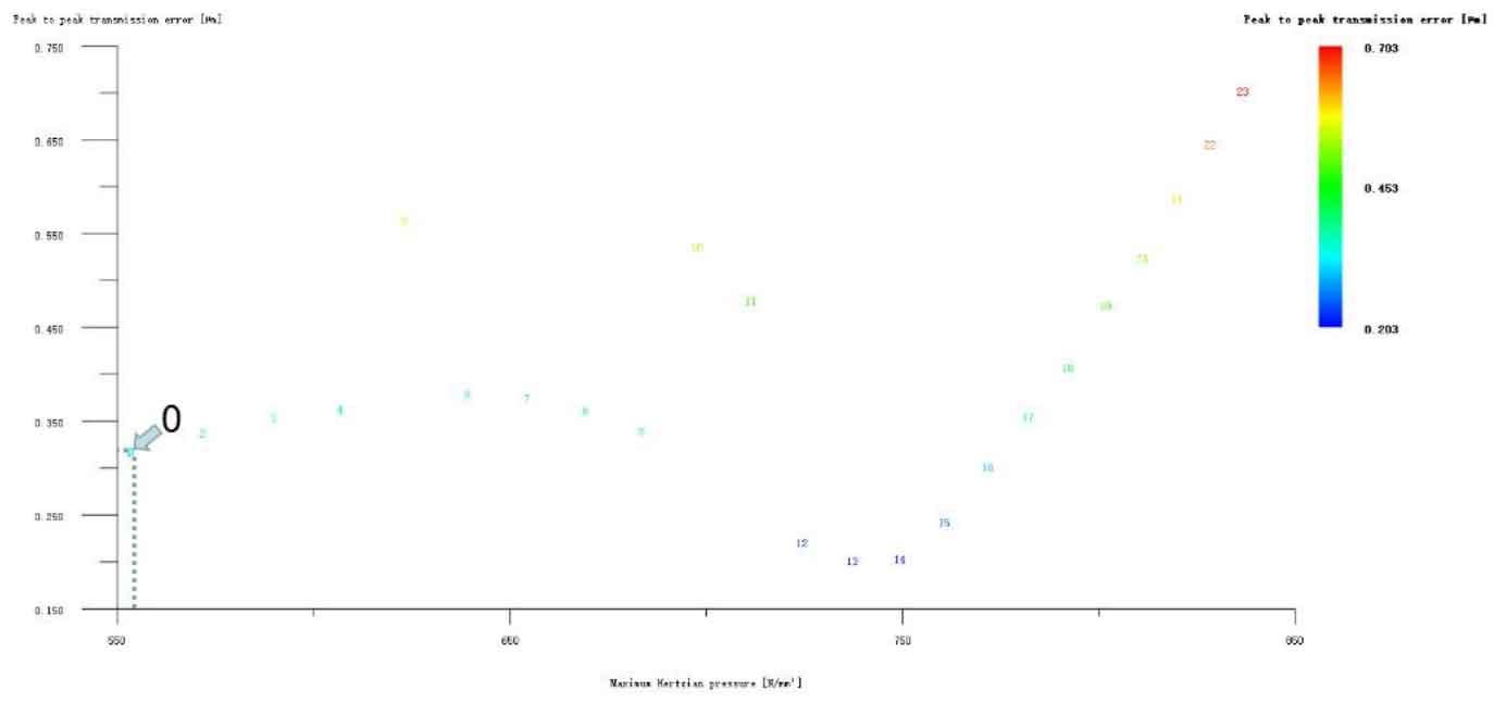
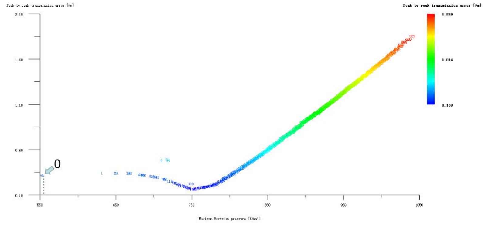
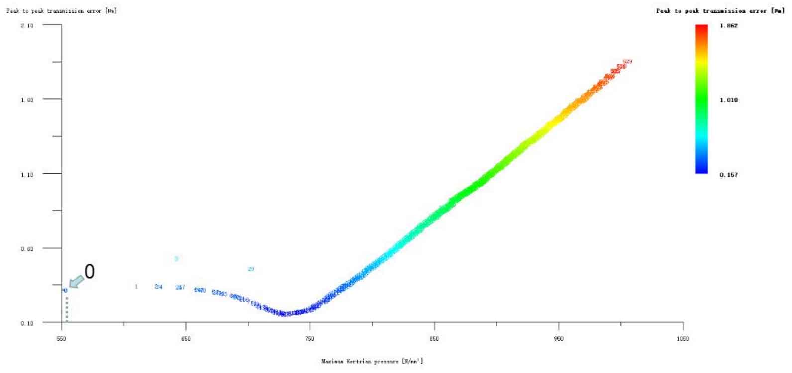
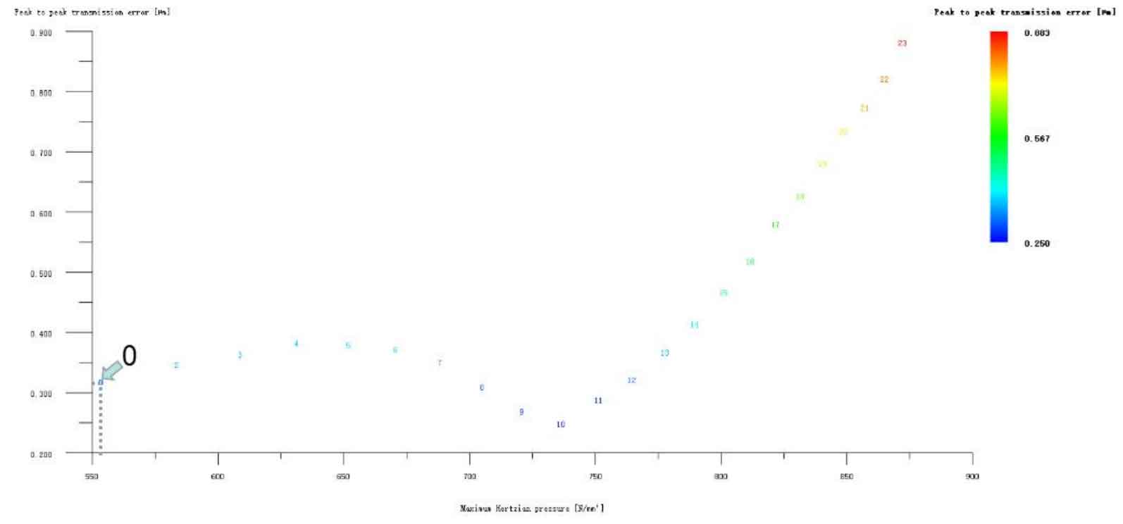
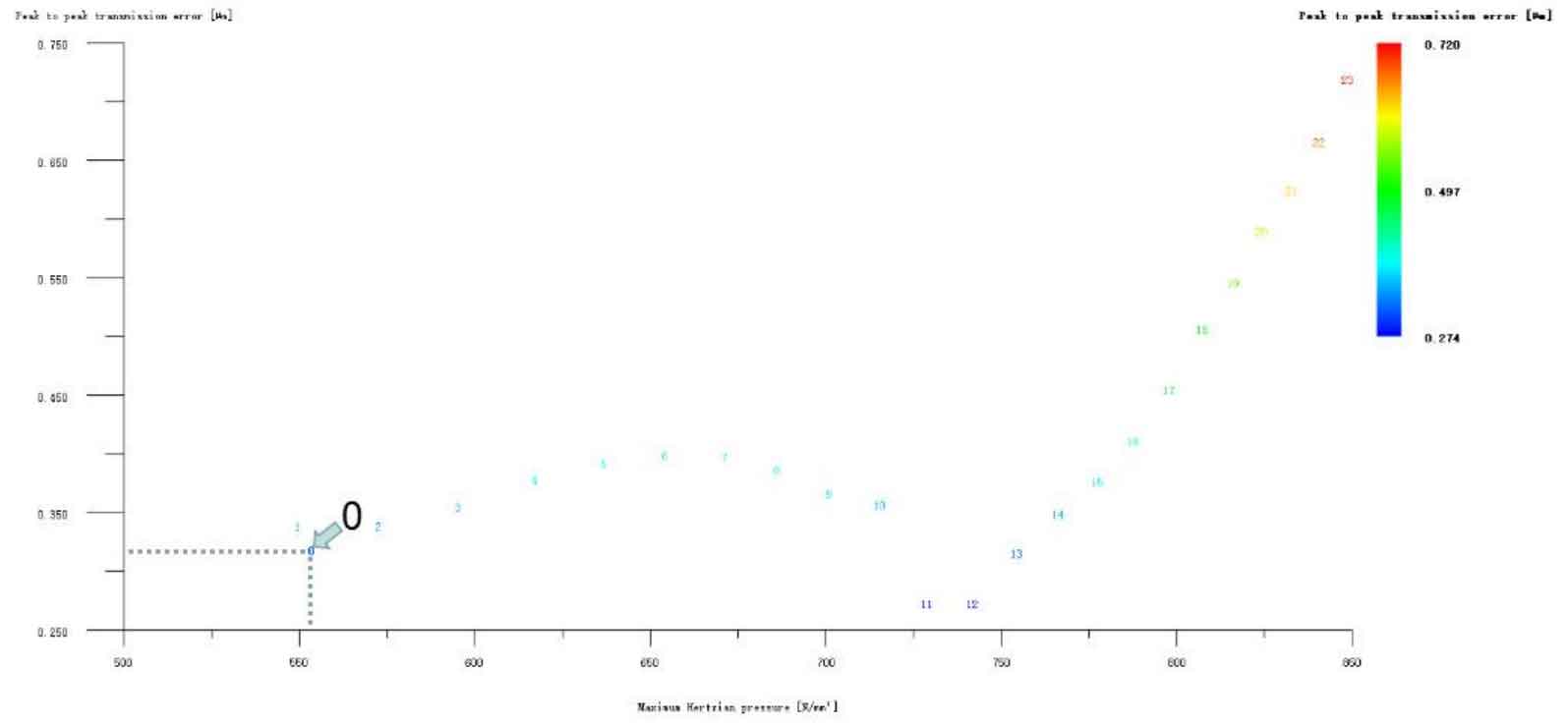
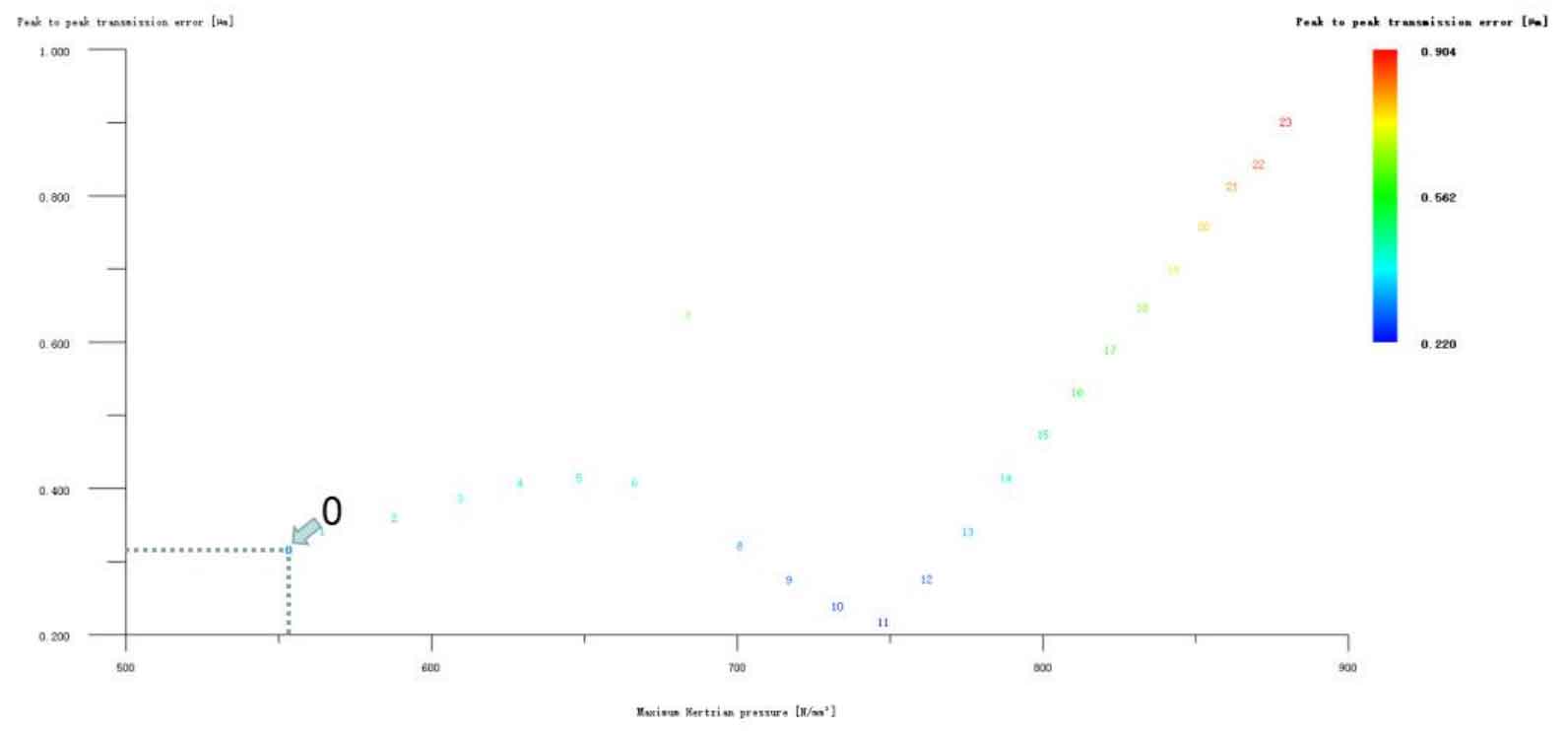
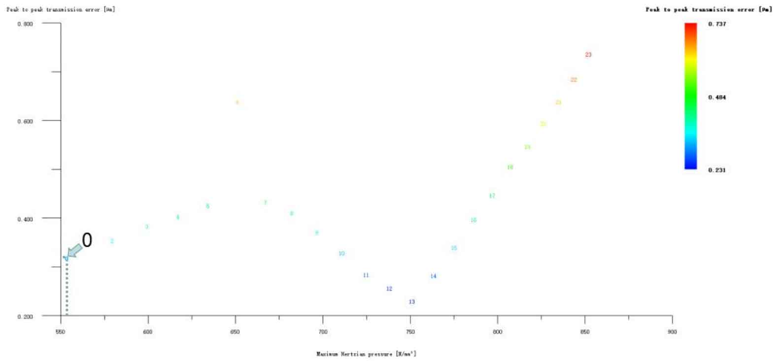
(3) Single helical gear tooth profile optimization modification+tooth direction drum modification

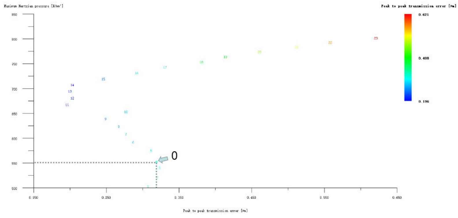
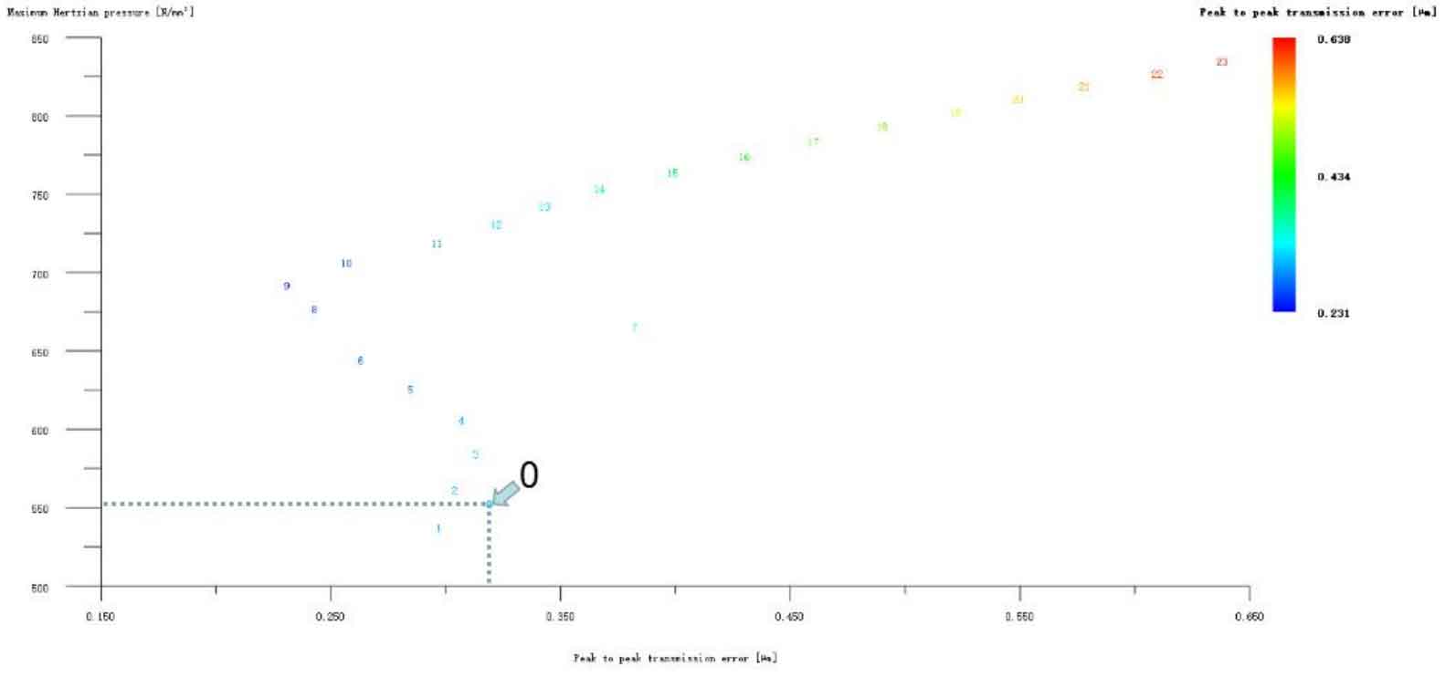
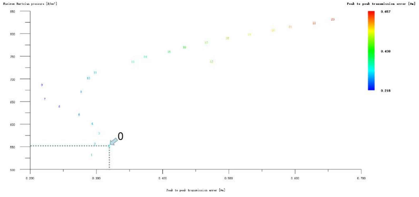
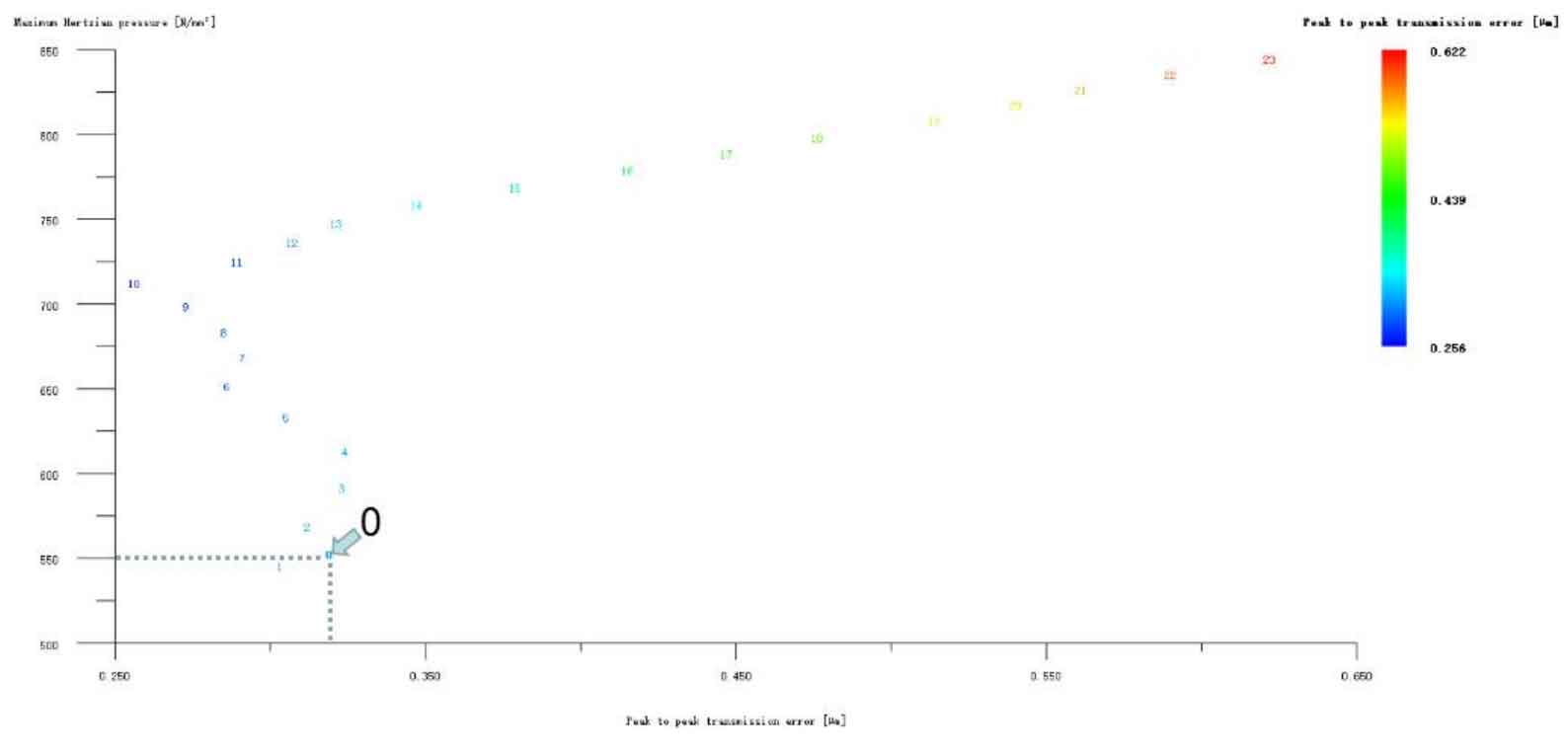
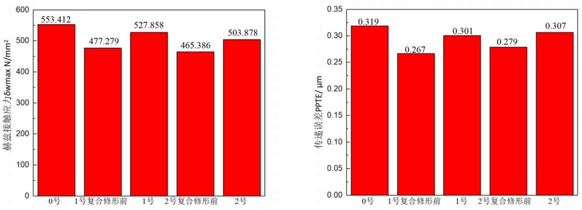
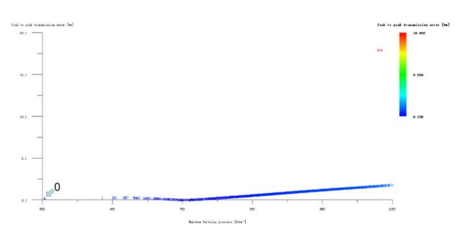
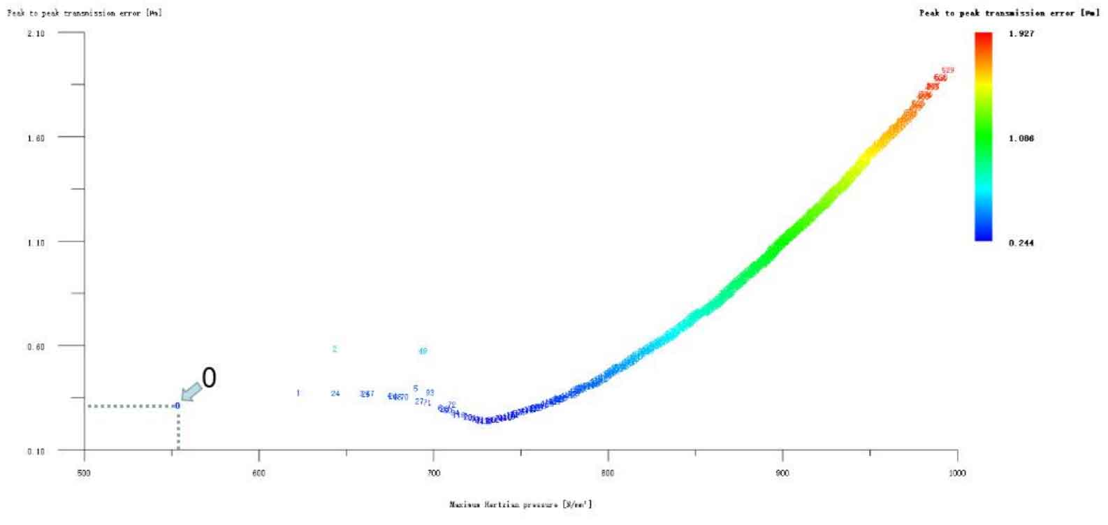
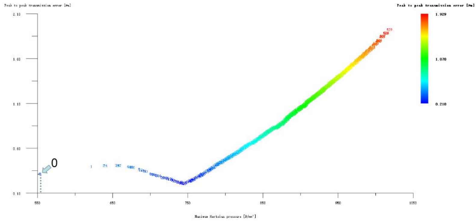
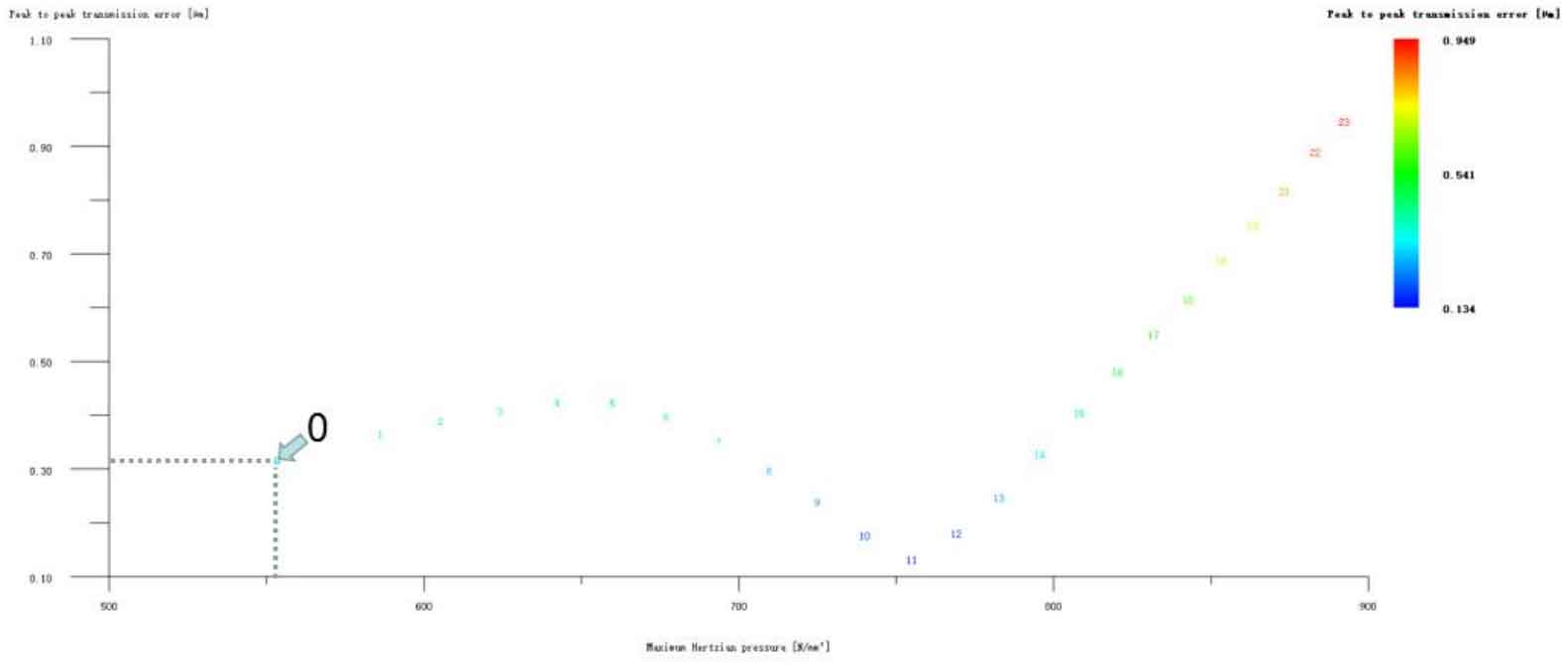
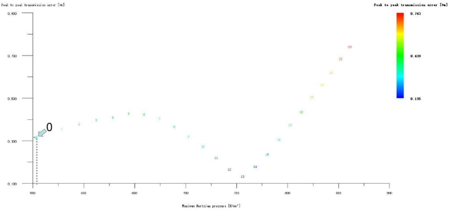
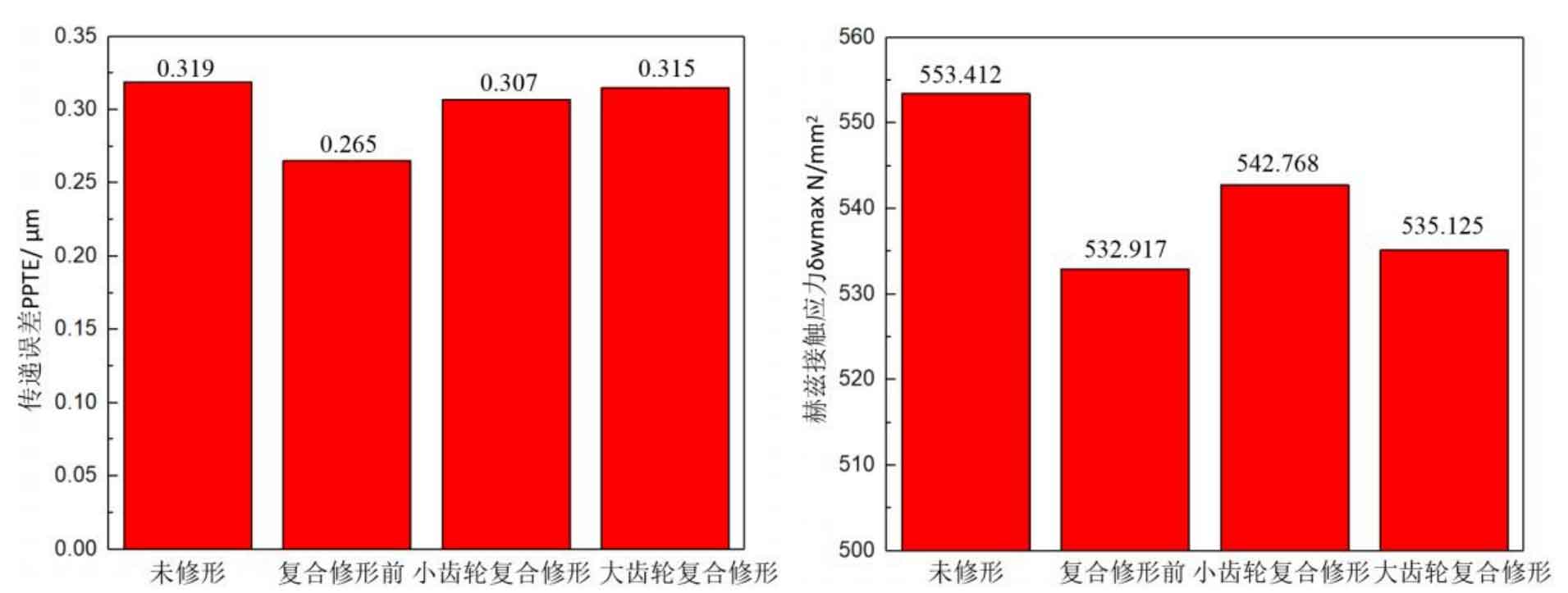
Figure 12 (a), Figure 12 (b), Figure 12 (c), Figure 12 (d) and Figure 12 (e) respectively refer to the drum shaped modification of pinion profile and tooth direction, the drum shaped modification of big gear profile and tooth direction, the crown arc of long profile and tooth direction of big gear plus the drum shaped composite modification, the crown involute of long profile and the drum shaped composite modification, and the crown arc of long profile and the drum shaped composite modification. Obviously, Scheme 1 in Fig. 12 (a), Scheme 1 in Fig. 12 (b), Scheme 1 in Fig. 12 (c), Scheme 1 in Fig. 12 (d) and Scheme 1 in Fig. 12 (e) are the optimal schemes for each composite modification mode. For the convenience of analysis, these optimal schemes are arranged in order as No. 1, No. 2, No. 3, No. 4 and No. 5, of which No. 0 represents no modification. The meshing performance of the front and rear parts of each scheme is shown in Figures 13 and 14. It can be seen from Fig. 3.59 that the transmission error can be greatly reduced after the optimized modification of the addendum arc, involute, and broken line arc of the long tooth profile of the helical gear pair, and then the drum shaped composite modification of the tooth direction (No. 3, 4, and 5 schemes), so as to achieve the goal of optimizing the transmission error and contact stress of the modified helical gear pair. However, according to Figure 14, if the tooth profile of a certain gear of the helical gear pair is drum shaped, it is not worth considering the tooth direction drum shaped composite modification (No. 1 and No. 2 schemes), because its transmission error and Hertz contact stress are significantly increased compared with those before the composite modification. Therefore, No. 3, No. 4 and No. 5 can be used as the optimization scheme of composite modification, and their detailed modification parameters and performance are shown in the table.
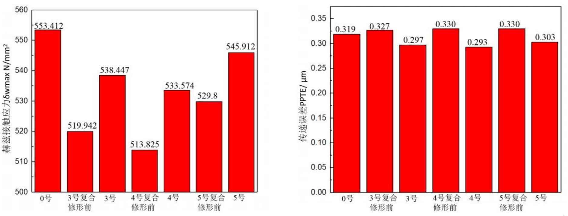
| Programme | Modification mode | Modification amount of driving wheel(μm) | Modification amount of driven wheel(μm) | Transmission error(μm) | Hertz contact stress(N/mm2) |
| 1 | Long tooth profile addendum arc+tooth direction drum | 0 | 3+3 | 0.297 | 538.447 |
| 2 | Long tooth profile addendum involute+tooth direction drum | 0 | 3+3 | 0.293 | 533.574 |
| 3 | Long tooth profile tooth crest fold line arc+tooth direction drum | 0 | 3+3 | 0.303 | 545.912 |