
As shown in the figure, the tooth surface load distribution of No. 0 unmodified, No. 1 optimization scheme and No. 9 optimization scheme is the three-dimensional figure of contact spot.
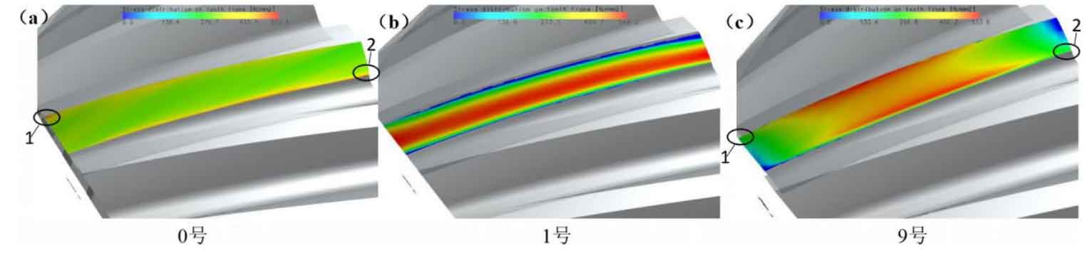
From Figure (a), it can be found that there is a large load and uneven distribution around the tooth top and root of the unmodified helical gear, especially at 1 and 2 sharp weak parts where the load distribution is red, which is easy to make the gear wear or even break due to the eccentric load of the gear teeth during the meshing transmission process, and the final service life and meshing stability are reduced.
At first glance, it seems that the load of No. 1 optimization scheme (Figure (b)) is more serious (the red part becomes more), but these loads are mainly concentrated in the middle of the gear teeth with large bearing capacity, and gradually spread to the fragile tooth top and root, and the maximum load on the tooth surface decreases, which will help to reduce the sudden change of the load on the tooth surface to a certain extent, so as to improve the gear meshing transmission performance.
Due to the adoption of the drum shaped composite modification in the tooth direction, the load in the No. 9 optimization scheme spreads evenly in both directions along the shaft from the center of the gear tooth width, significantly improving the load distribution in the sharp and weak parts such as 1 and 2.