
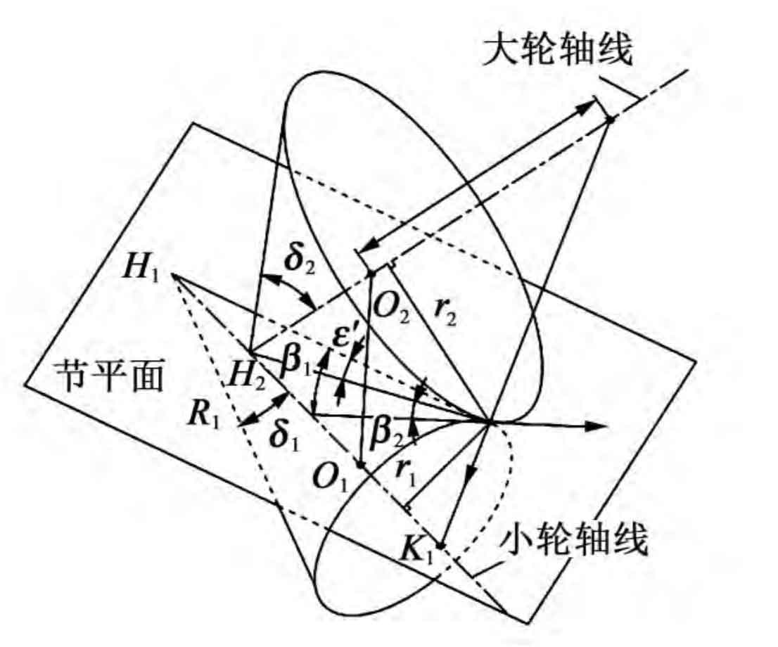
As shown in the figure, the geometric relationship of hypoid gear pitch cone is shown. The pitch circle radius r1 of the small wheel, the node radius r2 of the large wheel, and the cone angle of the large wheel pitch are given δ 2. Conical angle of small wheel pitch δ 1. Helical angle of big wheel β 2. Small wheel helix angle β 1. Pitch of big wheel R2, pitch of small wheel R1, offset angle ε ※ and the spatial location of the intersection O1 and O2.
In combination with the design research and standard specifications of quasi double curved surface at home and abroad, we propose a calculation method for the spiral angle of small gears by presetting the spiral angle of large gears to meet the limit normal curvature radius conditions, by giving the basic design parameters of gear blanks, according to Gleason’s calculation formula for hypoid gear blanks and the characteristics that the super reduction ratio is greater than that of hypoid gears, The geometric parameters of the hypoid gear pair with super reduction ratio can be calculated.
The design parameters of hypoid gears with constant height tooth super reduction ratio mainly include helix angle, pitch cone angle, tooth width, pitch, pressure angle and working tooth height. Because it is an equal height tooth, the root cone angle and face cone angle are equal to the pitch cone angle. In addition, when determining the above-mentioned gear blank parameters, the phenomenon of undercutting in the machining of hypoid gears should be avoided.
Before the wheel blank design of hypoid gears with equal high tooth super reduction ratio, the number of teeth z2 and z1 of big and small gears and the shaft intersection angle should be determined Σ, Offset E and gear rotation.
According to the knowledge of space geometry, the position of a point in space must be determined by three independent parameters. Similarly, when designing hypoid gears with super reduction ratio, the node position is determined by the offset angle of the pinion shaft section η 1. Small wheel helix angle β 1 and the radius r2 of the big wheel node. According to the load capacity of hypoid gears, the pitch radius of the big wheel can be determined as a basic parameter; Then the pitch cone angle of the big wheel can be estimated according to the formula, including:
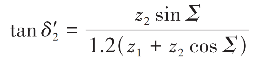
Where, Σ Is the axis intersection angle.
From the above data, we can get the initial value of big wheel node radius r2 and small wheel offset ε’ 0, respectively:
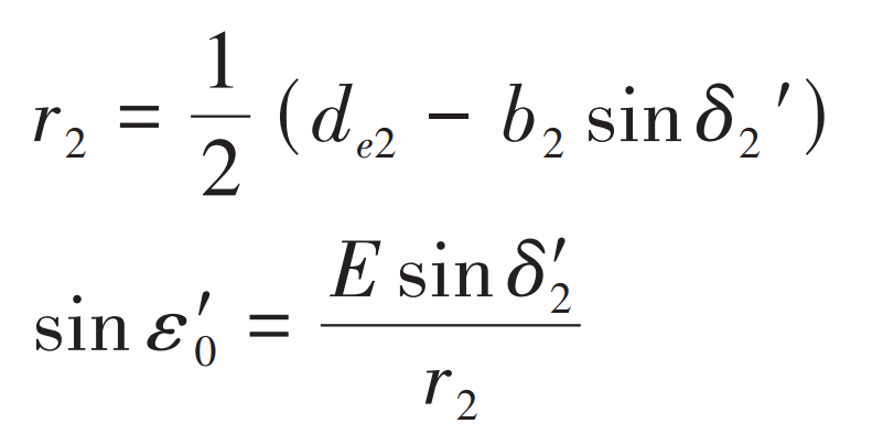
Where, de2 is the diameter of large wheel pitch circle; B2 is the tooth width of large gear; E is the offset distance.
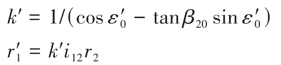
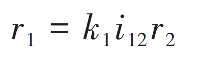
The initial value of the spiral angle of the small wheel is preset β 20=35 °, then the initial value of enlargement coefficient k ‘and the initial value of small wheel pitch circle radius r’1 can be obtained, namely:
The offset angle of the small wheel shaft section is obtained by iteration and preset η 1=0, its initial value is calculated as follows:
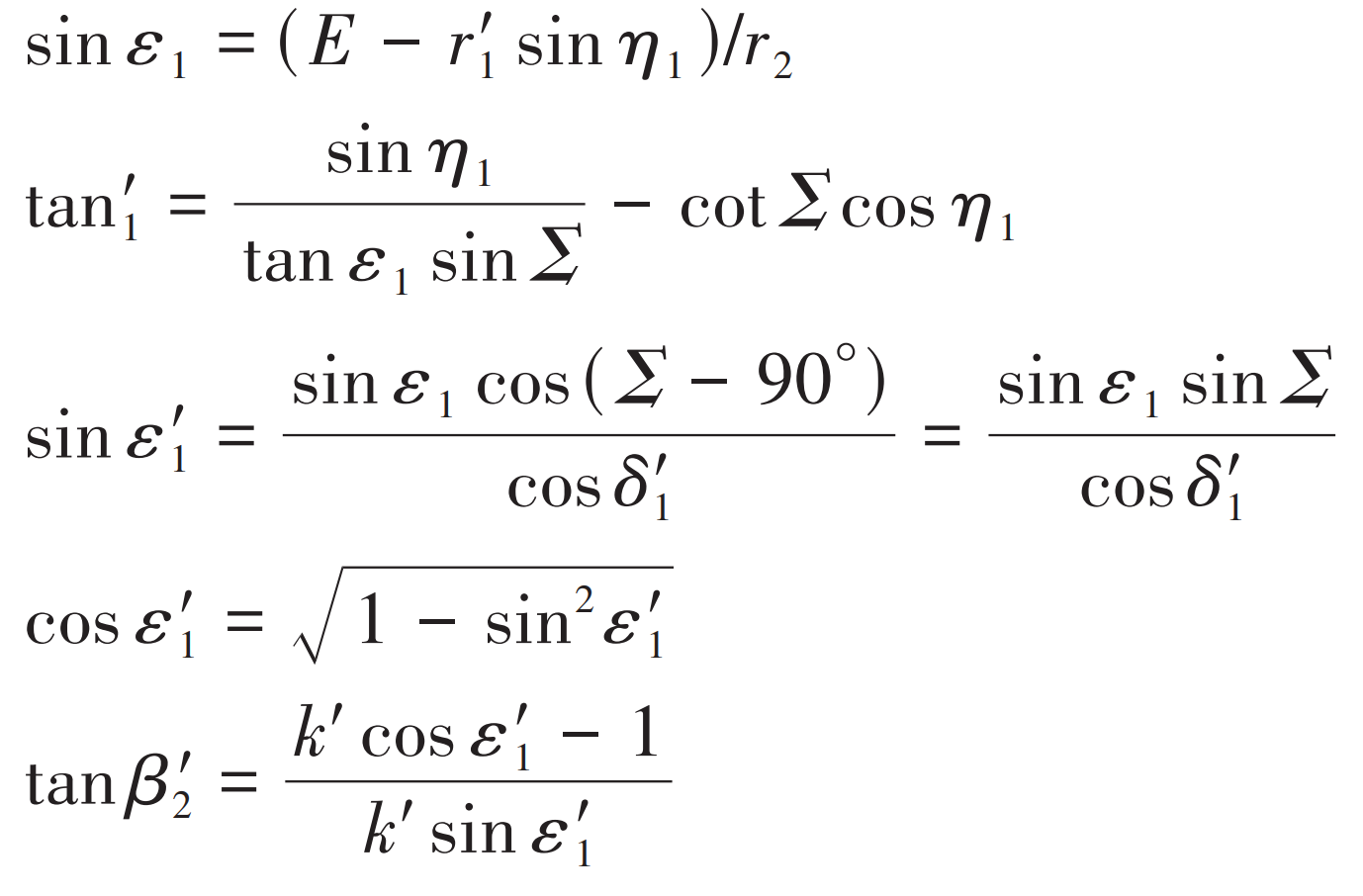
If | tan η 1| ≤ 0.01,tan η 1=± 0.011, the sign value is the same as the sign of the formula.
When tan η 1<0 or tan η When 1>0, get ε、δ 1、 ε ´、 β The approximate values of 1 are:
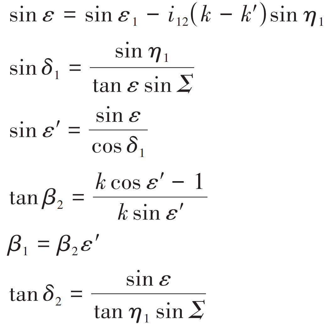
Helical angle of big wheel calculated according to formula β’ 2 Not necessarily equal to expected helix angle β 20. The pitch circle diameter of the small wheel can be corrected by modifying the enlargement factor. Let the modified amplification coefficient be k=1/(cos ε’ 1 – tan β 20 sin ε’ 1), compare it with k ‘=1/(cos ε’ 1 -tan β’ 20 sin ε’ 1) By subtracting, new enlargement coefficient and small wheel pitch diameter can be obtained. By:
Where, k1 is the enlargement coefficient.
Can be calculated again ε、δ 1、 ε ´、 β Value of 1. yes:
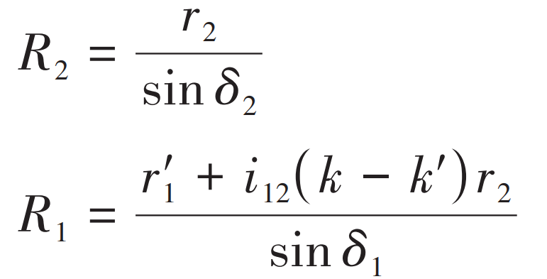
Then, the value of r ∗ is obtained according to the calculated value.
After the iteration results meet the requirements, the determined basic parameters of hypoid gear blank with super reduction ratio are obtained, and the blank dimensions of large and small wheels are obtained through further calculation, as shown in the table.
| Project | Pinion | Wheel |
| Number of teeth | 2 | 60 |
| Modulus/mm | 7.809 | 7.809 |
| Normal modulus of midpoint/mm | 5.961 | 5.961 |
| Tooth surface width/mm | 88.19 | 47.80 |
| Offset/mm | 133.84 | 133.84 |
| Pressure angle (/°) | 20.00 | 20.00 |
| Axis intersection angle (/°) | 90.00 | 90.00 |
| Outer taper distance/mm | 165.81 | 238.86 |
| Tooth tip height/mm | 11.90 | 0.00 |
| Root height/mm | 2.63 | 14.53 |
| Full tooth height/mm | 14.53 | 14.53 |
| Outer diameter/mm | 74.38 | 468.44 |
| Pitch cone angle (/°) | 8.88 | 78.68 |
| Face cone angle (/°) | 8.81 | 78.68 |
| Root cone angle (/°) | 8.81 | 78.68 |
| Pitch cone vertex to intersection point/mm | -9.58 | 4.99 |
| Face cone vertex to intersection point/mm | 6.69 | 4.99 |
| Root cone vertex to intersection point/mm | -13.16 | 1.89 |