
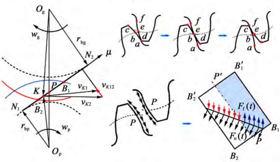
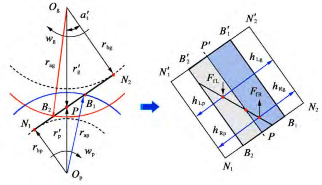
It can be seen from Figure 1 that the relative sliding directions on both sides of the pitch line on the meshing surface are different, which leads to the change of friction on both sides of the pitch line. If it is specified that the friction on the contact line on the right side of the pitch line is positive, and the friction on the contact line on the left side of the pitch line is negative; The friction torque direction is positive when it is the same as the helical gear rotation direction, and negative when it is opposite. Assuming that the friction force is evenly distributed along the contact line, the contact line at any time is divided into two left and right segments by the nodal line as the boundary, and the friction force can be regarded as the concentrated force acting on the midpoint of each segment of the contact line. By calculating the tooth surface friction coefficient and friction arm at the midpoint of each contact line on both sides of the pitch line, the friction force and friction moment on each contact line on both sides of the pitch line can be obtained, as shown in Figure 2. definition μ Is the end face engagement position coordinate, and its size is the distance from the intersection point of gear tooth contact line and end face on the base circle to the entry end B2. The friction force and friction torque of a single pair of teeth are the difference between the friction force and friction torque generated by the left and right contact lines. The calculation formula is:
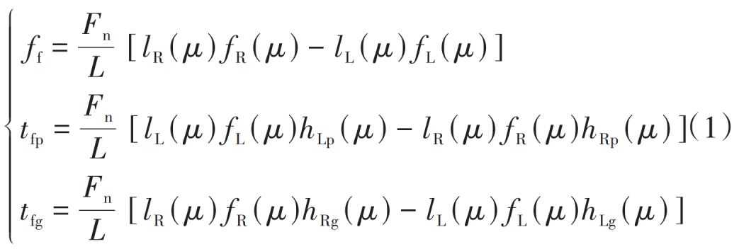
Where, ff is the friction force of single pair of teeth, N; Friction torque of single pair of teeth of tfp and tfg main and driven wheels respectively, N · mm; Fn is the normal force acting on the helical gear, N; L is the total length of contact line at that time, mm; LL and lR are the length of each contact line on the left and right sides of the section line respectively, mm; FL and fR are the friction coefficients at the midpoint of each contact line on the left and right sides of the section line respectively; HLi and hRi (i=p, g) are the friction arm at the midpoint of the contact line on both sides of the pitch line of the main and driven wheels respectively, mm.
According to the periodicity of helical gear engagement, the total friction and friction torque within a base circle pitch are:
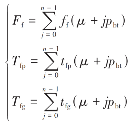
Where, Ff is the total friction force, N; Tfp and Tfg are the total friction torque of the main and driven wheels respectively, N · mm; N is the number of teeth engaged at the same time; Pbt is the base circle pitch of the end face, mm.