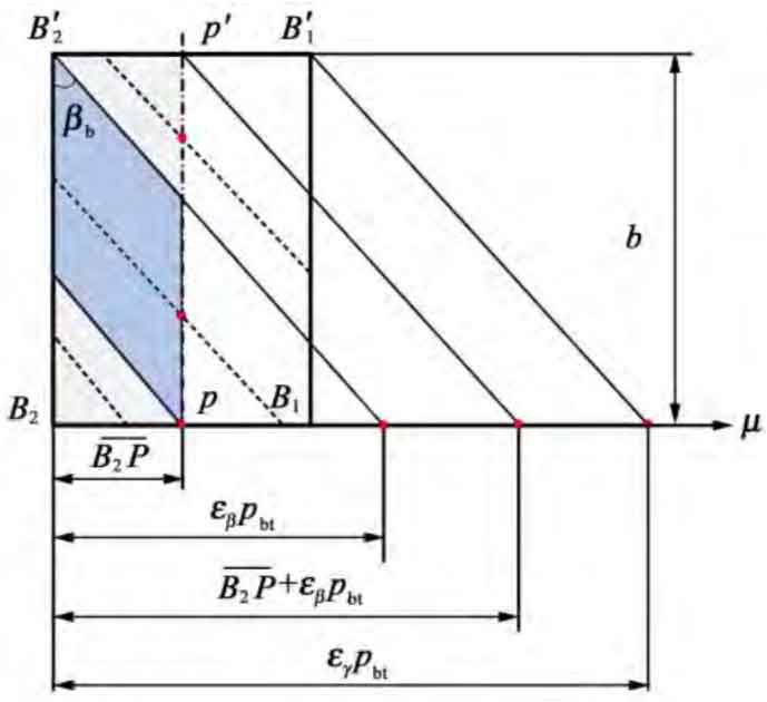
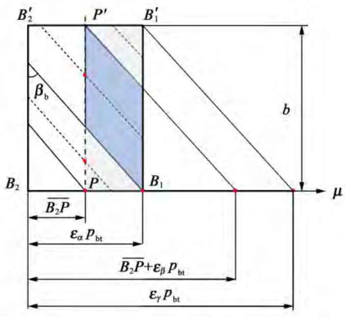
As shown in Figure 1, the length of the contact lines on the left and right sides of the pitch line changes during the engagement of a single pair of helical gears from entry to exit. In Figure 1, εα Is the end face coincidence; εβ Is axial coincidence; εγ Is the total coincidence; β B is the helix angle of the base circle, (°); B is the tooth width, mm. According to the geometric relationship in Figure 2, it can be concluded that:
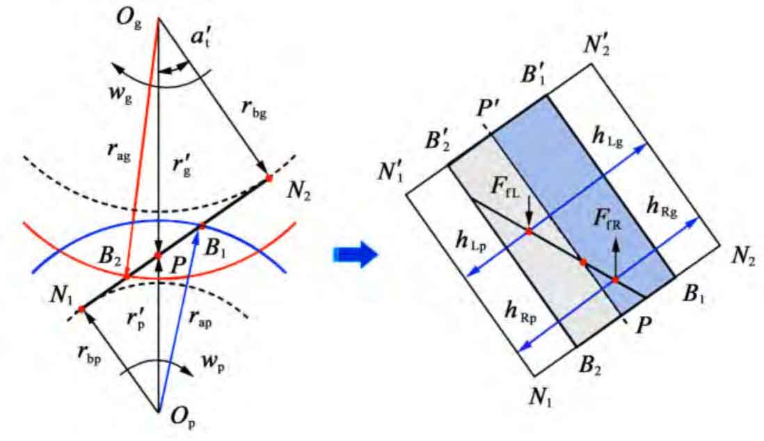
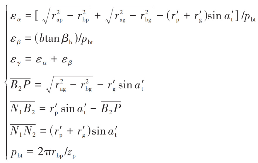
Where, zp is the number of teeth of helical driving gear.
As shown in Figure 1 (a) and Figure 1 (b), the length lL and lR of the helical gear engagement single pair of teeth contact line on the left and right sides of the pitch line are respectively:
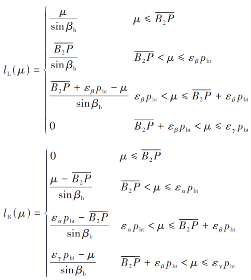
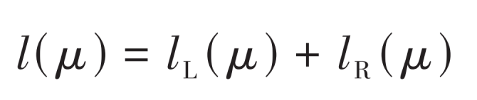
The total length l of helical gear meshing single pair of teeth contact line is:
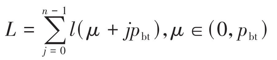
The total contact line length within one base circle pitch is: