
In the process of helical gear meshing, the friction coefficient of tooth surface will change significantly with the change of speed, load distribution on tooth surface, tooth profile surface topography and other factors. On the basis of elastohydrodynamic lubrication, Xu H et al. added factors such as tooth surface roughness, lubricating oil viscosity, tooth surface equivalent curvature radius, etc., and gave an improved fitting formula of elastohydrodynamic lubrication friction factor, namely:
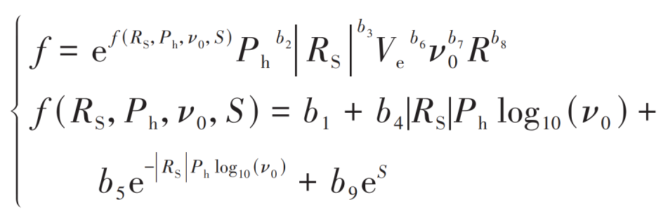
Where, ν 0 is the dynamic viscosity of lubricating oil, 103 Pa · s; S is the root mean square value of the comprehensive roughness of the tooth surface, μ m; R is the normal equivalent curvature radius of the tooth surface, m; Ph is the maximum Hertz contact pressure on the tooth surface, GPa; Ve is the entrainment speed, m/s; RS is the slip roll ratio; B1~b9 are coefficients related to lubricant type, and their values are shown in Table.
| Calculation coefficient | b1 | b2 | b3 | b4 | b5 | b6 | b7 | b8 | b9 |
| Value | -8.92 | 1.03 | 1.04 | -0.35 | 2.81 | -0.1 | 0.75 | -0.39 | 0.62 |
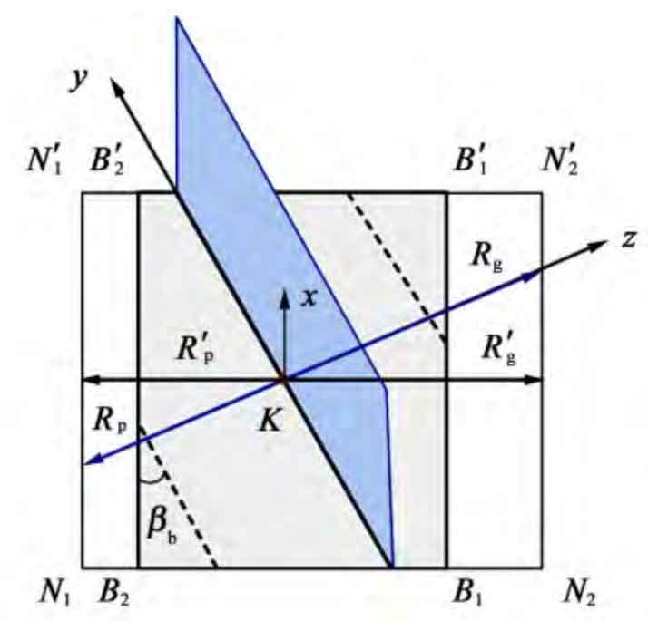
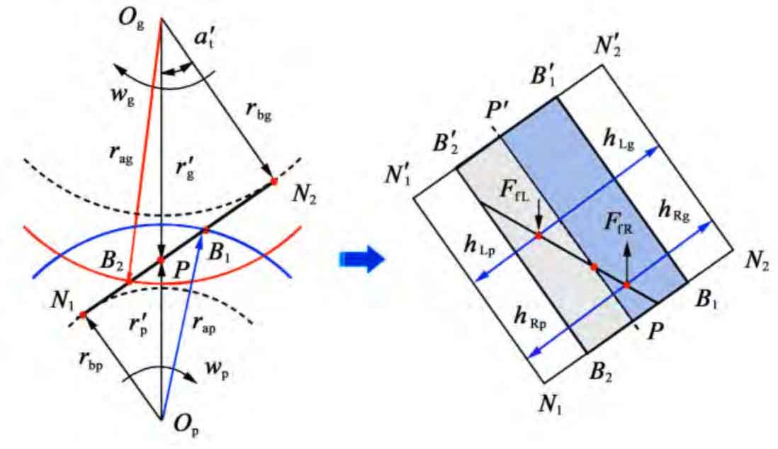
Figure 1 shows the dynamic coordinate system on the engagement plane. At any meshing point K, the coordinate system is established with K as the coordinate origin. The direction along the contact line is the y-axis, the direction perpendicular to the y-axis in the meshing plane is the z-axis, and the direction perpendicular to the y-axis in the tangent plane is the x-axis. According to the meshing characteristics of helical gears, the x direction is the rolling speed direction of helical gears, and the z direction is the normal direction of load action.
It can be seen from Figure 1 that the normal equivalent radius of curvature at any meshing point K is:
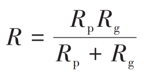
According to the geometric relationship in Figure 1, it can be obtained that:
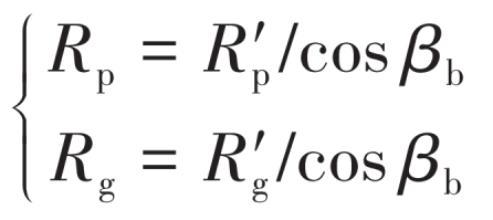
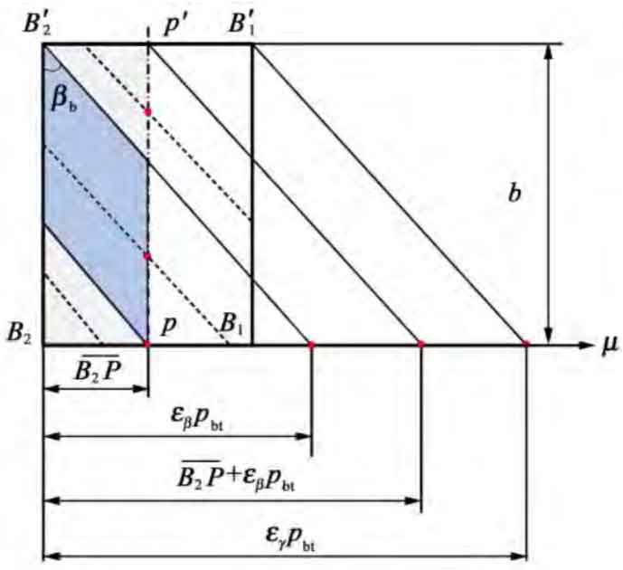
As shown in Figure 2 and Figure 3, the radius of curvature of the end at the midpoint of the contact line on the left and right sides of the pitch line is:
Other parameters are calculated as follows:
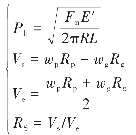
Where, E ´ is the equivalent elastic modulus; Wp and wg are the angular velocities of the main and driven wheels respectively, rad/s; Vs is the sliding speed, m/s.
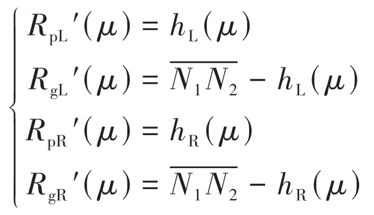
According to the formula, the tooth surface friction factors fL and fR at the midpoint of the contact line on the left and right sides of the pitch line can be obtained.
Substitute lL, lR, L, fL, fR, hL, hR into the formula to obtain the friction force and friction torque of a single pair of teeth and a total meshing tooth pair.
In the process of helical gear meshing, the friction force perpendicular to the direction of the meshing line will cause the friction torque around the helical gear rotation center, thus causing the change of the meshing force on the tooth surface. According to the torque balance of driving wheel:
Where, Tp is the input torque of driving wheel, N · mm; Tfp is the friction torque of driving wheel, N · mm; Rbp is the base circle radius of the driving wheel, mm.