
According to the established finite element simulation model of hypoid gear with super reduction ratio, the Transient structural module is imported to study the change of contact load under transient load.
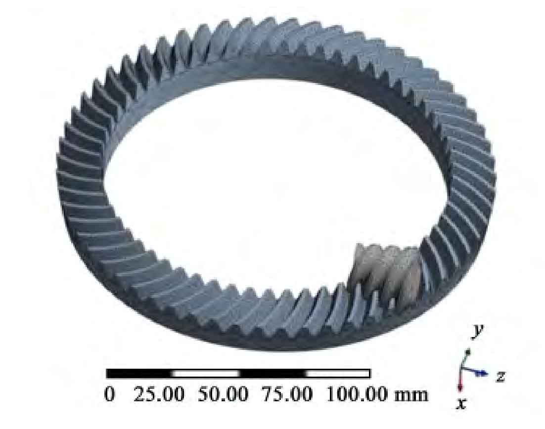
The three-dimensional assembly model of hypoid gear with super reduction ratio is meshed, as shown in Figure 1. Among them, there are 72357 units and 121602 nodes (the gear mesh division has met the quality required for gear analysis).
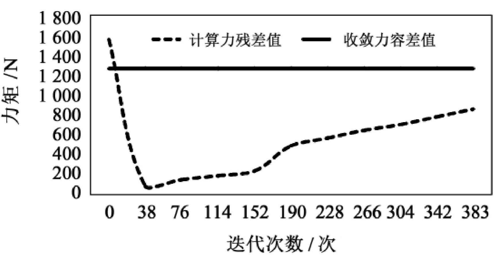
In the process of finite element program calculation, the nonlinear iteration curve is generated by the accumulation of iteration times. When the force criterion is greater than the residual value of the calculated force, it can be seen from the nonlinear iteration curve shown in Figure 2 that when the residual value is always greater than the convergence value in each substep of the analysis process, the convergence performance is good, which proves the correctness of the nonlinear calculation method and constraint application of the super reduction ratio hypoid gear.
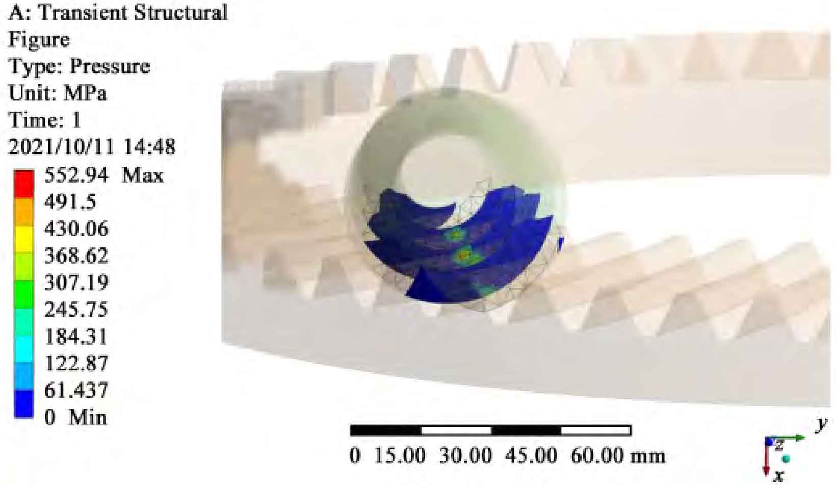
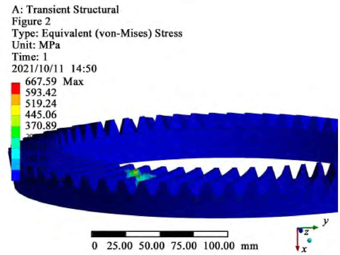
The tooth surface contact area distribution of hypoid gear with super reduction ratio obtained through simulation calculation is shown in Figure 3, and the equivalent stress diagram of hypoid gear with super reduction ratio is shown in Figure 4.
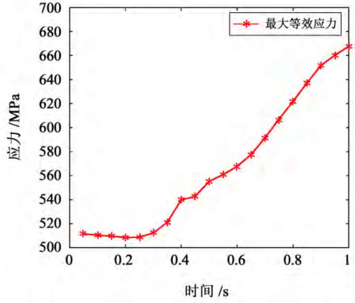
By analyzing the meshing process of hypoid gears and sorting out the data of the change of the maximum equivalent stress with time, the change curve obtained is shown in Figure 5.
It can be seen from Figure 3 that the maximum contact stress occurs near the tooth root surface. The maximum contact stress value is 552.94 MPa, which is less than the allowable stress of hypoid gear (861 MPa). The tooth surface will be subject to pitting corrosion due to fatigue due to changing contact stress. The maximum contact stress of this analysis is the same as the position where pitting corrosion first occurred, indicating that the analysis results are valid.
It can be seen from Figure 4 that the maximum equivalent stress of the tooth surface is 667. 59 MPa, which occurs at the contact and meshing position of the big wheel and the small wheel, and is less than the allowable stress value of 861 MPa, proving that the hypoid gear meets the strength requirements.
It can be seen from Figure 5 that the hypoid gears generate large stress when they are just engaged (in operation, the meshing hypoid gears make the driven wheel move through contact with the increase of the driving wheel speed. In the view of contact dynamics, it is actually a process of contact impact). The subsequent stress fluctuation value is within 100 MPa, and then tends to be stable.
This is because when the hypoid gear starts to mesh, the driving wheel has a certain impact force, which causes the hypoid gear to mesh with a large stress value, and the rear gear starts to mesh stably, making the equivalent stress value stable.