
In actual machining, the normal tooth profile of double circular arc gear is circular arc. Therefore, the end face profile of the double circular arc gear is established by using the tooth profile and helix to establish the model, and the end face equation is obtained through the tooth surface equation of the circular arc gear.
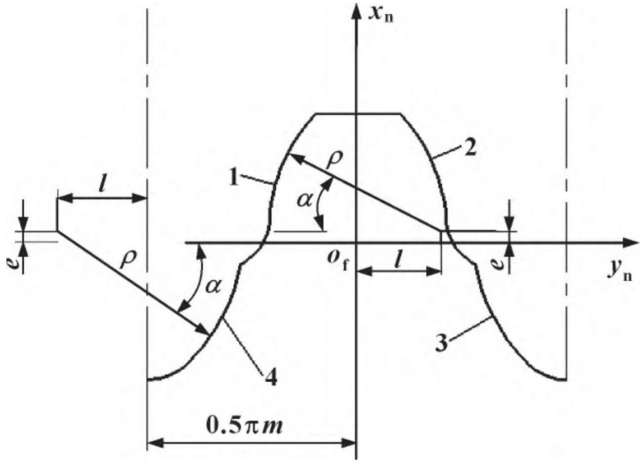
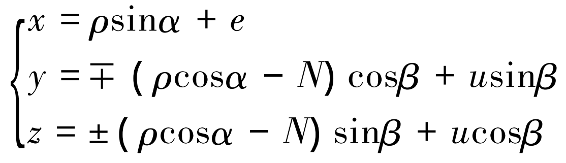
Establish the fixed coordinate system Sn of gear teeth, draw four working arcs of the basic tooth profile of double circular arc gear teeth as shown in Figure 3, and the expression of the forming surface can be uniformly expressed as:
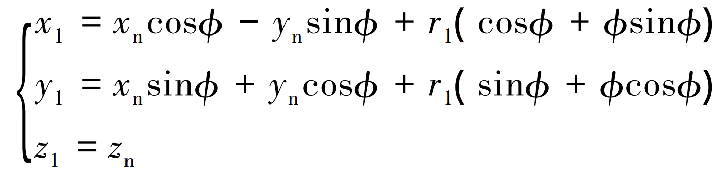
The fixed gear tooth coordinate system Sn moves the shaft to the gear center coordinate system S1:
The conjugate basic conditions during gear forming are:

After moving the expression formula of the forming surface from the fixed coordinate system of gear teeth to the center coordinate system of the gear, the simultaneous conjugate contact condition formula is solved, and the equation of the circular arc gear tooth surface is obtained as follows:
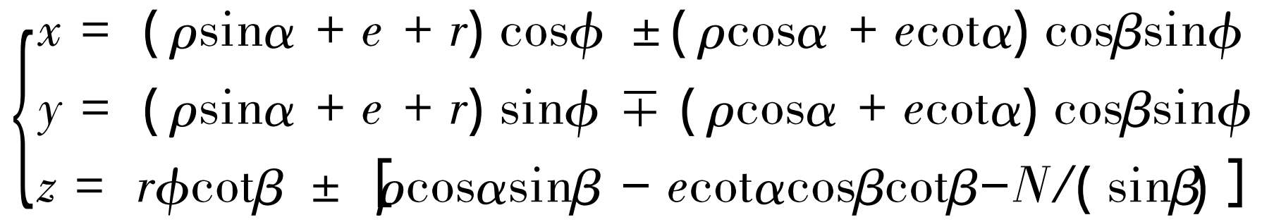
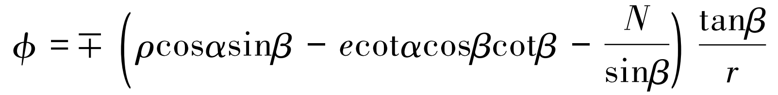
Where: double positive and negative signs, the upper represents the left tooth surface and the lower represents the right tooth surface; x. Y, z are coordinate points of tooth surface; ρ Is the arc radius; α Is the pressure angle; e. N is the center shift of the tooth profile; R is the pitch circle radius; φ Is the gear angle. Let the axial coordinate z=0 in the formula, and calculate the angle at the end face φ Value expression:
In MATLAB φ Values are substituted into x and y equations in tooth surface equation α The convex arc, connecting arc, concave arc and tooth root arc are calculated for parameter variables, and the coordinate points of each arc are extracted and imported into the modeling software to obtain the double arc gear model.