
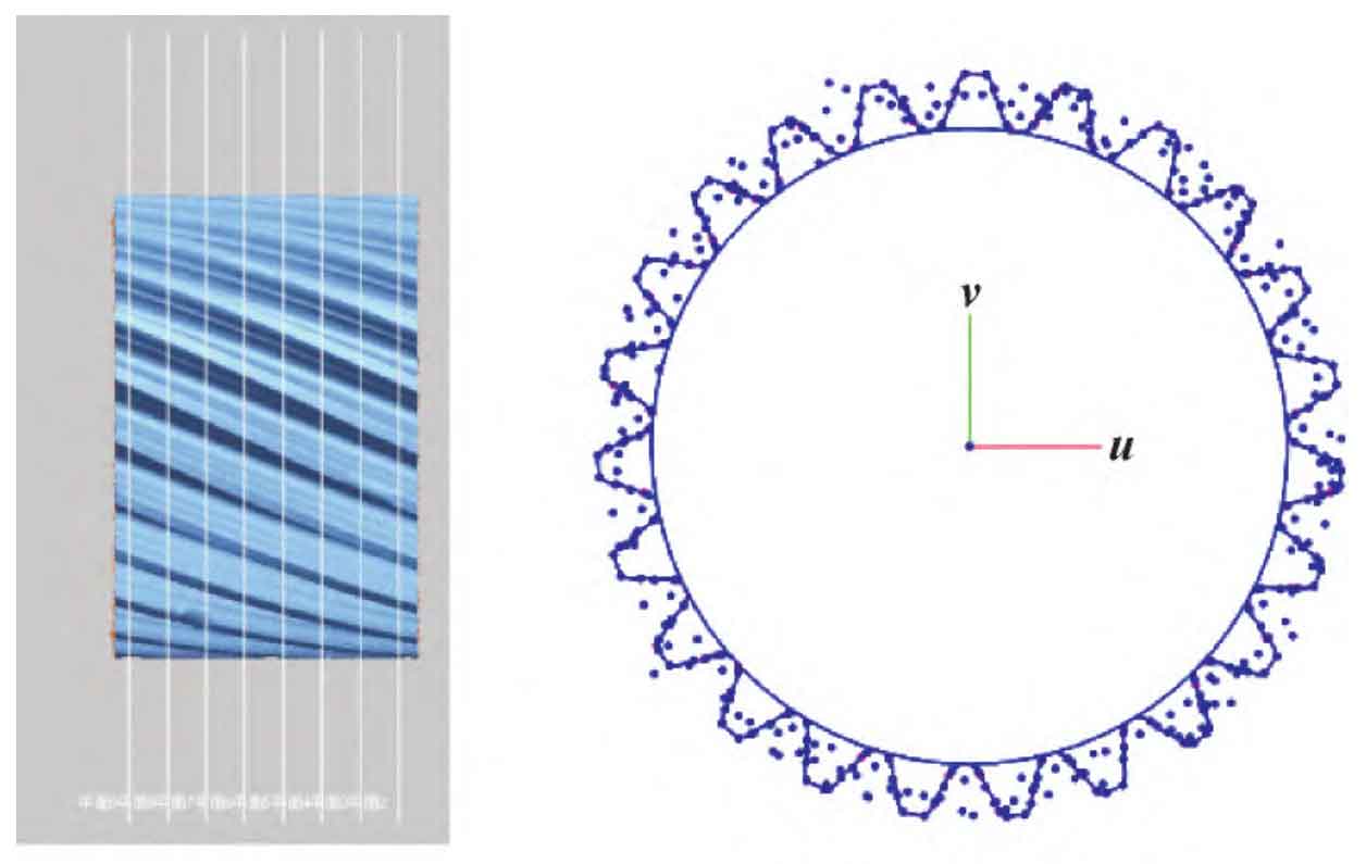
Measure the gear module. Take the effective meshing section of the gear and establish a section parallel to the end face. In order to avoid the influence of the chamfer of the gear tooth end face on the measurement, set the distance between the first section and the end face to be 5 mm, and set the spacing between other sections to be 10 mm. Create a patch sketch on each plane. Use the automatic sketch command to obtain the profile of the gear shaft section as shown in Figure 1 (a). Use the point on the profile root and the point on the top to fit the addendum circle and the root circle, as shown in Figure 1 (b). The measured radius data are shown in Table 1.
| Sketch No | Addendum circle radius | Root circle radius | Modulus |
| 1 | 60.333 6 | 51.506 9 | 4.413 35 |
| 2 | 60.382 7 | 51.494 3 | 4.444 20 |
| 3 | 60.352 8 | 51.524 5 | 4.414 15 |
| 4 | 60.345 3 | 51.535 7 | 4.404 80 |
| 5 | 60.402 7 | 51.532 6 | 4.435 05 |
| 6 | 60.363 3 | 51.564 3 | 4.399 50 |
| 7 | 60.383 0 | 51.553 2 | 4.414 90 |
The average calculated addendum circle radius is 60 366 2 mm, the average root circle radius is 51 530 21 mm。 The number of teeth is 23. The gear modulus is the standard value. According to the table, the second series modulus is 4 5 mm is the closest module, and the module of the gear shaft is determined to be 4 5 mm。
Measure the spiral angle of the gear reference circle. Select some tooth surface division fields, and fit the best surface for the division fields, as shown in Figure 2.
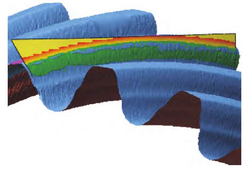
The gear cylindrical surface is established, and the current cylindrical helix is obtained by intersecting with the tooth profile surface, so as to calculate the helix angle of the cylinder. Select 3 gear teeth to measure the helix on both sides of the tooth surface. The current cylindrical surface radius r1=58 is obtained by fitting the surface offset of the tooth top cylinder with the method of domain division 338 77 mm。 The measured data and the calculated helix angle are shown in Table 2.
| Helix No | Spiral arc length/mm | Projection arc length of end face/mm | Cylinder helix angle/(°) |
| 1 | 84.367 904 | 34.480 684 | 24.122 841 |
| 2 | 84.232 874 | 34.147 979 | 23.916 215 |
| 3 | 84.348 376 | 34.432 738 | 34.093 099 |
| 4 | 84.355 372 | 34.449 793 | 24.103 665 |
| 5 | 84.358 696 | 34.458 266 | 24.127 122 |
| 6 | 84.393 124 | 34.541 804 | 24.160 645 |
Find the helix angle β’ The average value of is 24 087 263°。 The helix angle at the dividing circle obtained from the formula is:
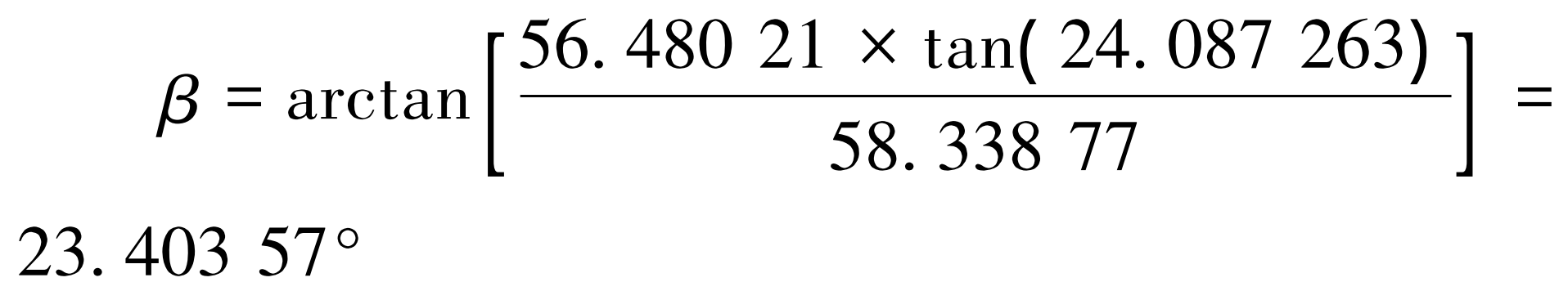
The current gear measurement helix angle and design helix angle β 0 =23. 411 Difference of 67 ° Δβ = 0. 008 1 °=0 ° 0 ’29’ ‘, relative error δ = 0. 34‰。