
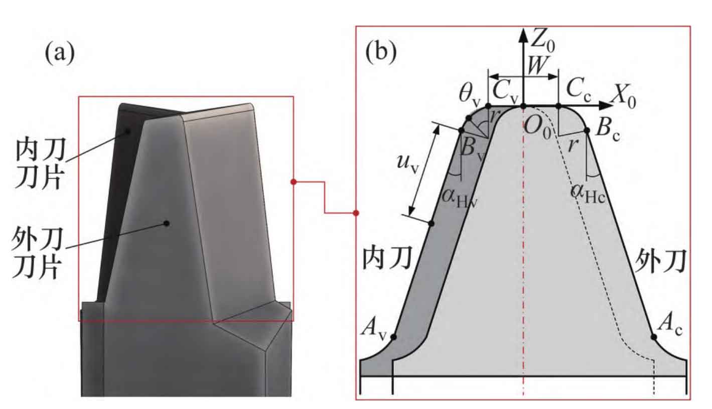
The double faced normal spiral bevel gear pinion uses a double faced cutter head. The schematic diagram of the normal section of the double faced cutter is shown in Figure 1. In the figure, the coordinate system S0 (X0, Y0, Z0) is fixedly connected to the blade. The coordinate origin O0 is located at the midpoint of the tip distance W of the double faced cutter head. The distance from O0 to the cutter head axis is the nominal radius R0 of the cutter head; AvBv and AcBc are the main cutting edge segments of the inner cutter and the outer cutter respectively, which are used to machine the working tooth surface of the spiral bevel gear pair; BvCv and BcCc are respectively the tool tip arc segments of the internal cutter and the external cutter, which are used to process the transitional arc segments of the spiral bevel gear pair; α Hv and α Hc is the pressure angle of main cutting edge of internal tool and external tool respectively; R is the arc radius of the inner and outer tool tips; Uv and θ V is the length from the inner tool to the cutting edge and the arc section of the tool finish.
The equations of the main cutting edge AiBi segment and the tip arc BiCi segment of the internal and external cutters of the large and small wheels are respectively:
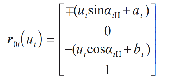
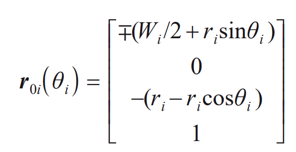
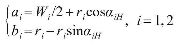
Where: i=1, 2, representing small wheel and large wheel respectively; Ui and θ I is the variable of the main cutting edge and the tool tip arc segment respectively; Both ai and bi are auxiliary parameters of the main cutting edge equation of the tool,
R0i (ui) represents the length of the main cutting edge AiBi section of the double-sided cutter, r0i( θ i) Represent tool tip arc Bi
Ci section length. The first symbol in Formula (1) and (2) shall be determined according to the following principle: negative for internal cutter and positive for external cutter.
The double double faced spiral bevel gear small wheel and large wheel are processed by generating method. The rotation direction of the small wheel is right rotation, and the rotation direction of the large wheel is left rotation. The processing coordinate system generated by the right rotation of the small wheel is shown in Figure 2. In Figure 2, the coordinate systems Sm (Xm, Ym, Zm) and Sc (Xc, Yc, Zc) are fixedly connected to the center of the machine tool and the cradle respectively; The coordinate system Se (Xe, Ye, Ze) is fixedly connected to the cutter head, the coordinate system Sp (Xp, Yp, Zp) is fixedly connected to the small wheel blank, and the coordinate systems Sk (Xk, Yk, Zk) and Sb (Xb, Yb, Zb) are auxiliary coordinate systems; The cutter and pinion gear blank are cut at point P; β 1 is the mid point spiral angle of the small wheel; SR1 is the radial cutter position of the small wheel; B1 is the bed; Q1 is the initial shaking table angle, γ M1 is the mounting angle of the machine tool; φ C1 and φ 1 is the rotation angle of the platform and the small wheel during processing.
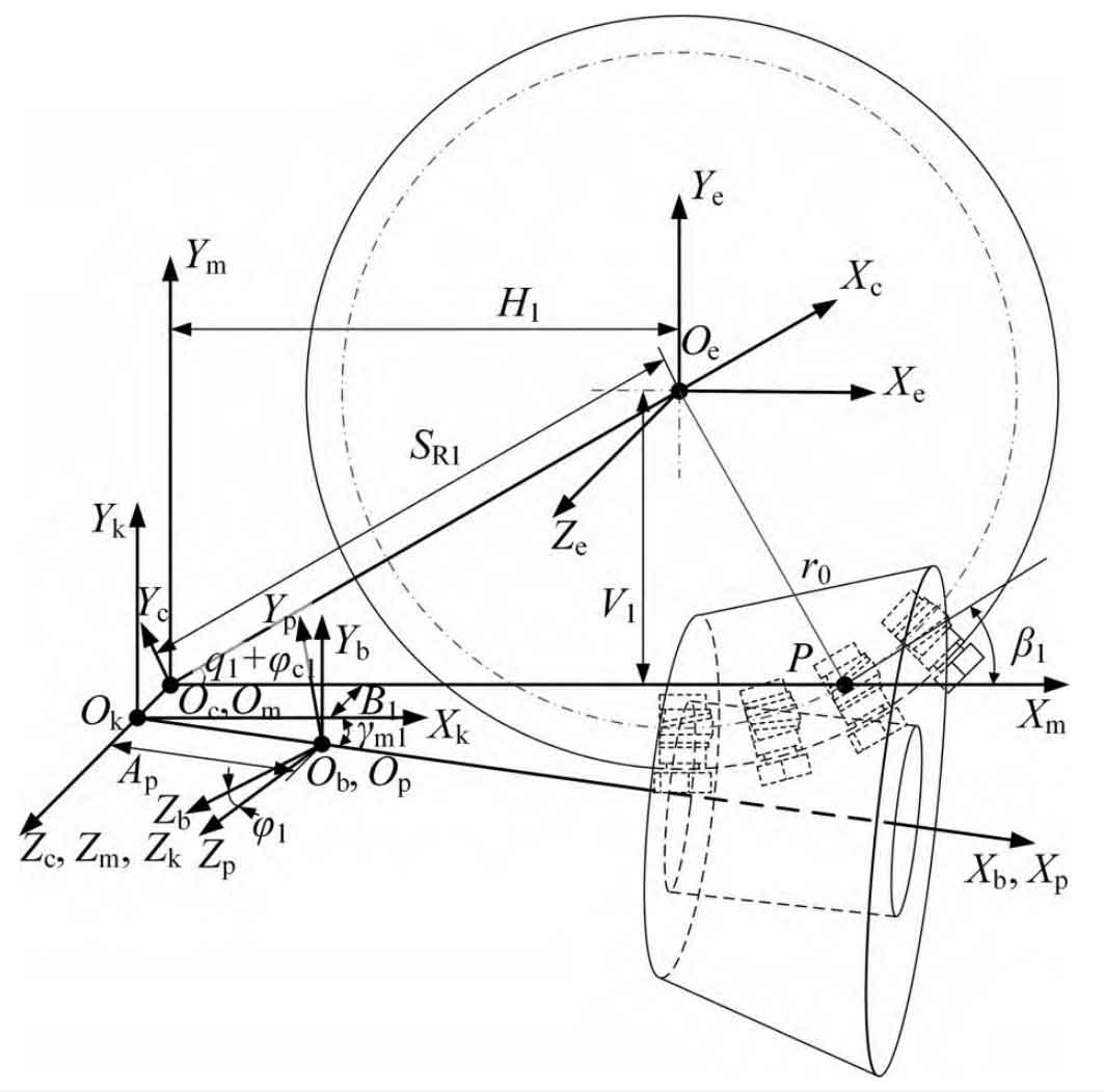
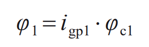
When machining the small wheel, the blank rotation angle φ 1 Rotation angle with swing table φ The relationship between c1 and roll ratio igp1 is:
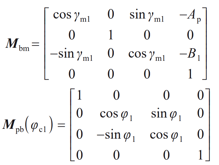
By simulating the spiral bevel gear machining process, the cutter equation is transformed to the blank coordinate system through coordinates, and the tooth surface equation after gear cutting can be obtained. The transformation matrix from the double faced cutter coordinate system S0 to the machine center coordinate system Sm is:
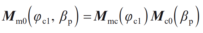
Including:

Where: β P is the rotation angle of the small wheel cutter.
The transformation matrix from the machine center coordinate system Sm to the small wheel blank coordinate system Sp is:
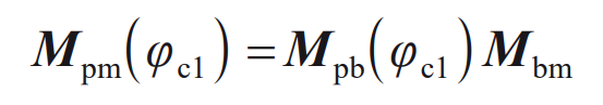
Including:
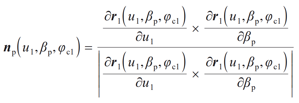
In the process of machining, there is relative rotation between the cradle and the blank, and the machining tooth surface needs to be solved by the meshing equation. Under the coordinate system SP, the normal vector expression of the tool is:
Based on the gear engagement theory, the engagement equation of spiral bevel gear is:
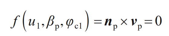
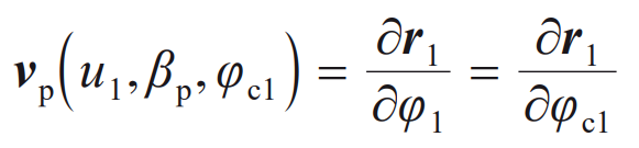
Where: vp is the relative speed of the small wheel cutting tool and the blank in the coordinate system SP,
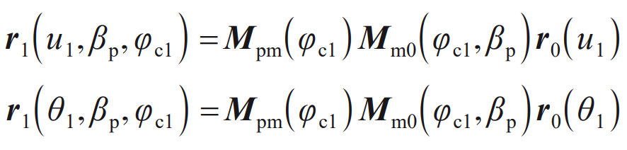
Using the meshing equation of spiral bevel gears, the angle of the rocker table during machining can be solved φ C1, the blank rotation angle can be obtained by substituting into the formula. The equations of the working tooth surface and the transition surface of the small gear obtained from the simultaneous formula are:
The machining process of the big wheel is similar to that of the small wheel. The rotation direction of the big wheel is opposite to that of the small wheel. Therefore, the signs of the initial cradle angle of the big wheel and the small wheel are opposite, that is, the initial cradle angle of the big wheel q2=− q1. Similarly, the tooth surface equation of the big wheel can be solved according to the above process.