
Table 1 shows the basic geometric parameters of the double double sided method small module spiral bevel gear pair. According to the double double sided method tooth cutting calculation table, the gear pair cutter parameters and machine tool processing parameters can be obtained as shown in Table 2.
| Gear | Number of teeth z/piece | Tooth width b/mm | Normal modulus of midpoint mn/mm | Pitch circle diameter at outer end of big wheel de2/mm | Midpoint helix angle β/ (°) | Direction of rotation | Outer end diameter dae/mm |
| Pinion | 10 | 7 | 0.9 | 48.8 | 35 | Dextral rotation | 15.7 |
| Wheel | 39 | 7 | 0.9 | 48.8 | 35 | Sinistral rotation | 48,9 |
The working surface of spiral bevel gear is generally the concave surface of the small wheel and the convex surface of the large wheel. Most of the time, the working surface participates in transmission. The calculation process of the contact meshing characteristics of the non working surface is consistent with the working surface. Therefore, only the impact of load and installation error on the meshing characteristics of the working surface of the gear pair is explored.
| Gear | Position | Tool tip distance W/mm | Nominal radius of cutter head R0/mm | Tool tooth angle α H/(°) | Radial cutter position Sr/mm | Initial shaking table angle q/(°) | Bed B/mm | Horizontal wheel position A/mm | Machine tool installation angle γ m/(°) | Roll ratio igp1 |
| Pinion | Concave | 0.6 | 19.1 | 18.3 | 18.2 | 58.9 | 0 | 0 | 13.4 | 4 |
| Pinion | Convex | 0.6 | 19.1 | 21.7 | 18.2 | 58.9 | 0 | 0 | 13.4 | 4 |
| Wheel | Concave | 0.6 | 19.1 | 18.3 | 18.2 | -58.9 | 0 | 0 | 71.4 | 1 |
| Wheel | Convex | 0.6 | 19.1 | 21.7 | 18.2 | -58.9 | 0 | 0 | 71.4 | 1 |
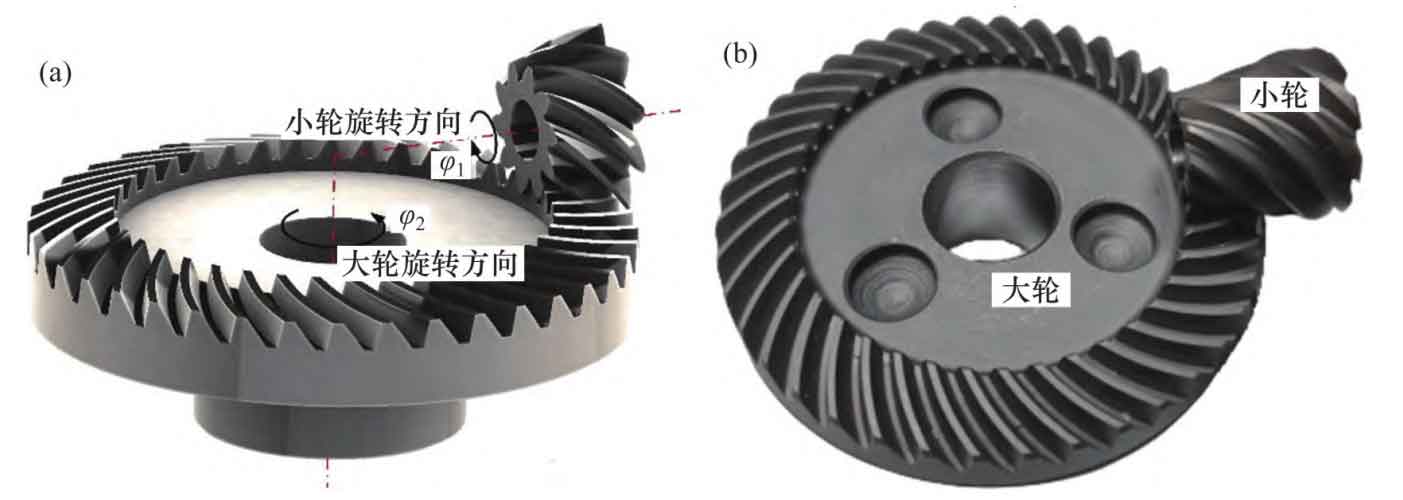
Based on the basic geometric parameters and machine tool processing parameters of the gear pair, combined with the mathematical model of the gear pair, the spatial point set of the gear pair can be obtained by using Matlab, and the three-dimensional solid model of the gear pair can be established by importing it into Creo, as shown in Figure 1 (a). Figure 1 (b) shows the gear pair of small module spiral bevel gear used for rolling. In actual production, in order to increase the strength and life of the pinion, the actual tooth width of the pinion is often greater than the design tooth width.
Import the three-dimensional solid model of spiral bevel gear into ABAQUS to establish the finite element model of gear pair, as shown in Figure 2. When building the three-dimensional model, the factors that have less influence on the simulation results, such as chamfer and blind hole of spiral bevel gear pair, are ignored.
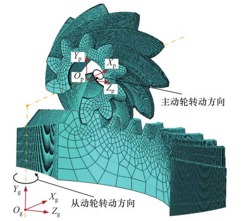
In order to save calculation cost, 9 teeth of large and small wheels are selected for calculation. The spiral bevel gear pair is made of 20CrMo, the elastic modulus is 210 GPa, and the Poisson’s ratio is 0.3. The small wheel and the large wheel are respectively coupled to the reference points Op and Og on their respective rotating axes. The mesh type is defined as hexahedral element C3D8R. A contact pair is established for the working tooth surface of the spiral bevel gear pair, and the pinion tooth surface is the driving surface. Apply rotation at coupling point of small wheel and load torque at coupling point of big wheel.