
When the rated load of small module spiral bevel gear pair is 3 N · m, the instantaneous contact ellipse of large gear tooth surface without considering the installation error of gear pair is shown in Figure 1 (a). To facilitate comparison, all the instantaneous contact ellipses of the same tooth surface at different times are projected onto the plane, and the projection of the engagement mark is obtained as shown in Fig. 1 (b). The spiral bevel gear pair shall be processed according to the parameters shown in Table 1 and Table 2, and correctly installed on the rolling machine. The rolling shall be carried out under the rated load. The actual rolling engagement mark is shown in Figure 1 (c). It can be seen from Fig. 1 that the simulated meshing mark and the actual rolling meshing mark are consistent in position, the length of the major axis of the instantaneous contact ellipse and the angle between the contact trace and the tooth root. The engagement mark is the projection of engagement mark as shown in Fig. 1 (b).
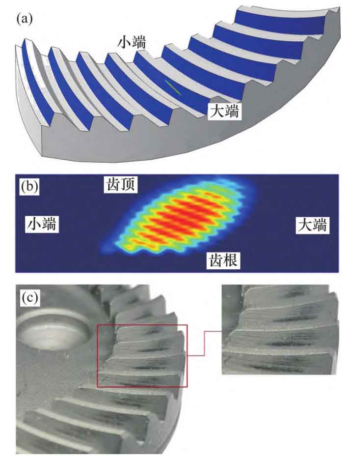
(b) Meshing impression projection;
(c) Counter roll engagement mark
As shown in Figure 2, the transmission error of spiral bevel gear pair under rated load is shown. The abscissa is the angle at which the small wheel rotates over 2 teeth. The peak to peak value of transmission error is about 2.7 × 10⁻⁵ rad。
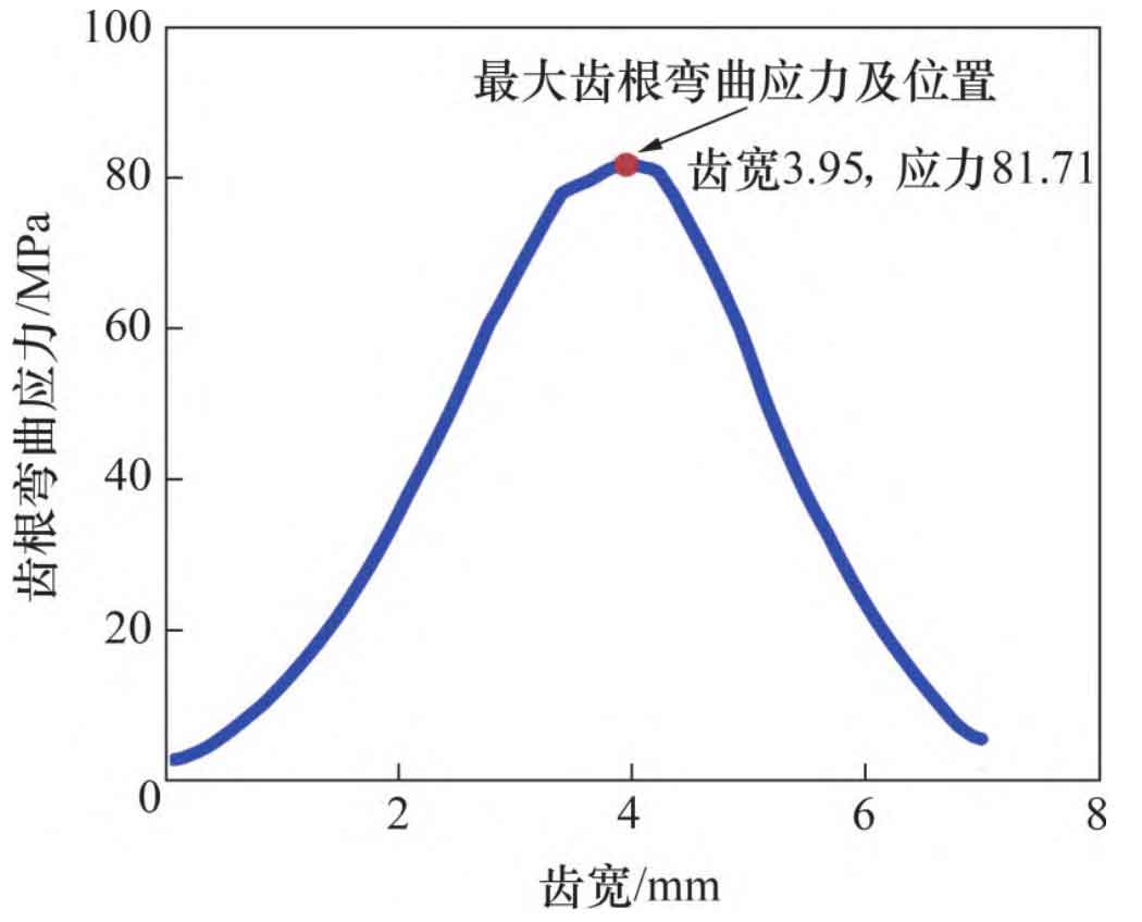
The tooth root bending stress of spiral bevel gear pair under rated load is shown in Figure 3, where the small end and the large end of the tooth surface are respectively indicated at 0 mm and 7 mm of the tooth width. It can be seen that under the rated load, the maximum tooth root bending stress is 81.7 MPa, which is about 4.0 cm wide.
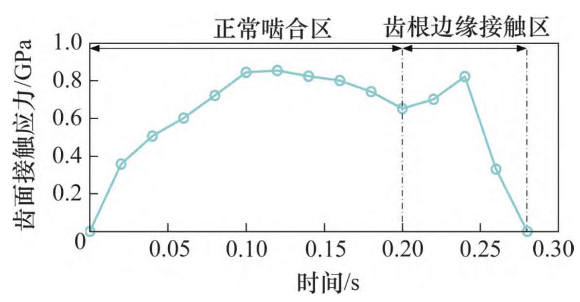
The tooth contact stress of spiral bevel gear pair under rated load is shown in Figure 4. It can be seen from Figure 4 that there is a clear boundary between the normal meshing area and the edge contact area. The tooth surface contact stress in the edge contact area increases, and the maximum tooth surface contact stress is 853.7 MPa.
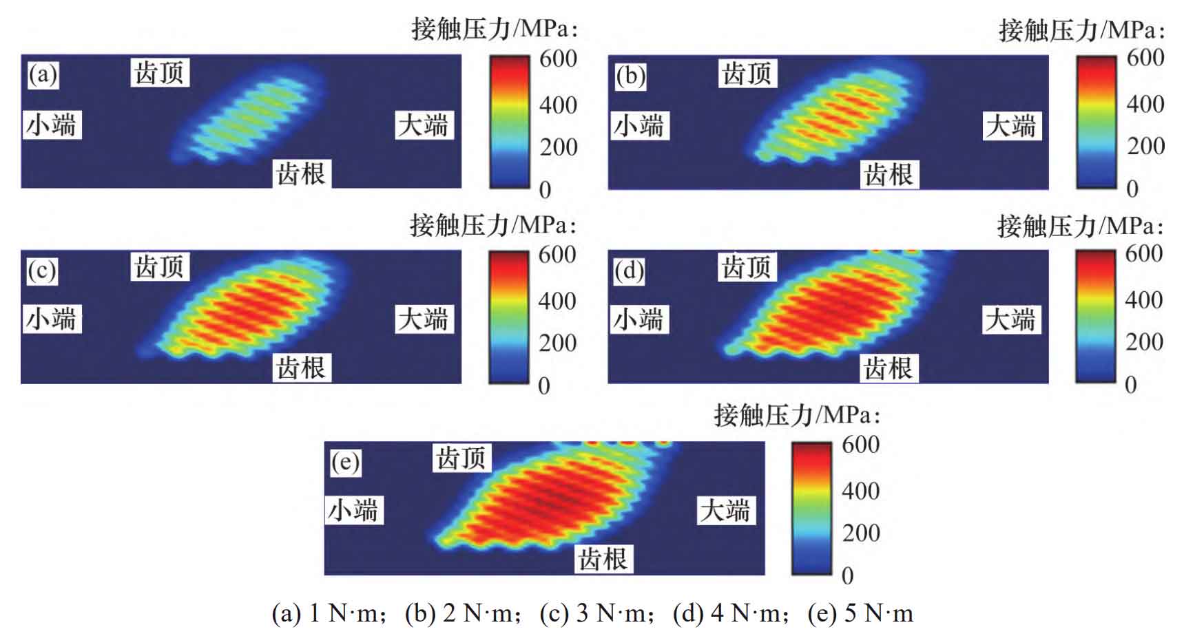
In order to explore the influence of load on the meshing characteristics of spiral bevel gear pairs, the meshing models of spiral bevel gear pairs under the working conditions of 1, 2, 3 (rated load), 4 and 5 N · m are calculated respectively. The comparison of the meshing marks of gear pairs under different loads is shown in Figure 5. It can be seen from Fig. 5 that with the increase of load, the position of engagement mark remains unchanged, the area of engagement mark, the length of the long axis of the contact ellipse and the high stress contact area all increase, and the edge contact area increases with the increase of load.
The influence of load on the transmission error of spiral bevel gear pair is shown in Figure 6. It can be seen from Figure 6 that when the load is 1 N · m, the peak to peak value of transmission error is about 3.2 × 10⁻⁵ rad; As the load increases from 2 N · m to 5 N · m, the peak to peak value of transmission error increases from 2.3 × 10⁻⁵ rad increased to 5.1 × 10⁻⁵ rad, the peak and peak values of transmission error generally show a trend of decreasing first and then increasing, and the variation trend of transmission error with load is consistent with that obtained by MAKAM through experiments.
The influence of load on the tooth root bending stress of spiral bevel gear is shown in Fig. 7 (a). It can be seen that the tooth root bending stress increases gradually with the increase of load from 1 N · m to 5 N · m. The influence of load on the contact stress of spiral bevel gear tooth surface is shown in Fig. 7 (b). It can be seen that the contact stress of tooth surface increases with the increase of load, the edge contact area gradually increases, and the time for the whole tooth surface to engage increases.
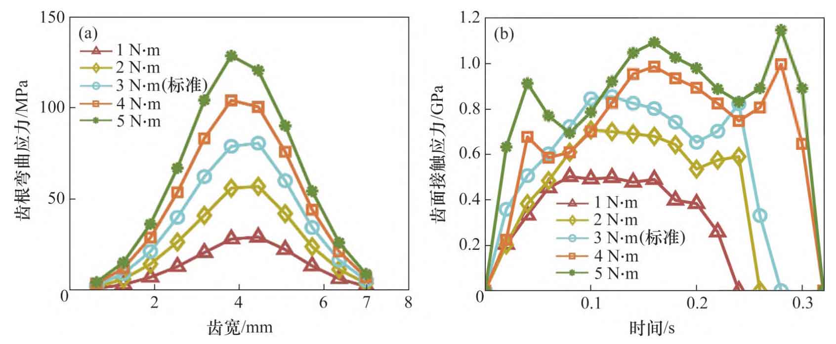
The maximum values of tooth root bending stress and tooth surface contact stress under different loads are shown in Table 3. It can be seen from the table that as the load increases from 1 N · m to 5 N · m, the maximum bending stress of the tooth root increases from 29.2 MPa to 128.6 MPa, and the maximum contact stress of the tooth surface increases from 501.1 MPa to 1146.2 MPa.
| Parameter | Load 1/(N · m) | Load 2/(N · m) | Load 3/(N · m) | Load 4/(N · m) | Load 5/(N · m) |
| Maximum root bending stress/MPa | 29.2 | 57.0 | 80.7 | 104.2 | 128.6 |
| Maximum contact stress of tooth surface/MPa | 501.1 | 706.4 | 853.7 | 995.5 | 1146.2 |