According to practical experience, contact fatigue often occurs in transmission gears. The table shows the basic parameters of the high-speed gear pair of the electric vehicle studied. Maximum contact stress of helical gear tooth surface during gear meshing σ H occurs on the pinion, and the contact fatigue dangerous position usually first appears in the single-tooth meshing area near the pitch line, so the node is taken as the gear tooth contact fatigue dangerous position. Based on Hertz contact theory, the maximum contact stress is taken as the basic value of the contact stress on the tooth surface of helical cylindrical gears. The contact stress calculation formula is as follows:
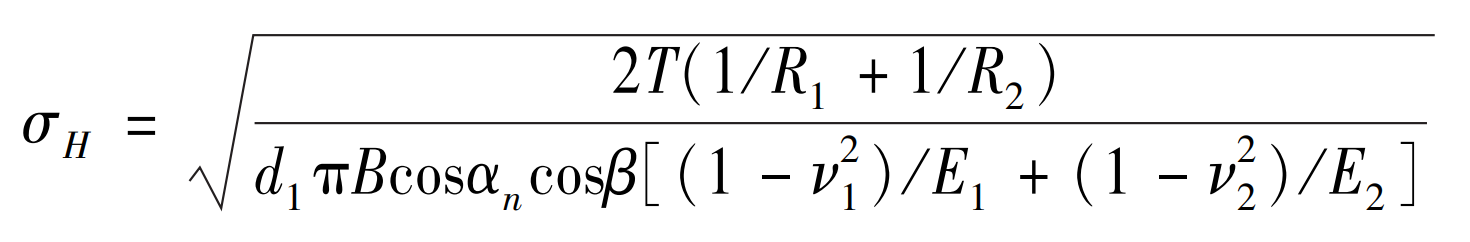
Where: σ H represents contact stress; T is the pinion torque; B represents tooth width; D1 represents the diameter of the pinion indexing circle; α N is the normal pressure angle; β Indicates helix angle; E1 and E2 respectively represent the elastic modulus of the two gears; ν 1 、 ν 2 is the Poisson’s ratio of two gears; The radius of curvature R1 and R2 of the two tooth profile contact points are calculated according to the following formula:
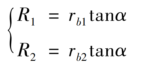
Where: the base circle radius of rb1 and rb2 gears respectively; α Indicates the meshing angle of two gears.
| Parameters | Value |
| Base circle radius rb1, rb2 / m | 0.02,0.084 |
| Normal pressure angle α t/ (°) | 20 |
| Face pressure angle α n/ (°) | 21.88 |
| Helical angle of indexing circle β/ (°) | 25 |
| Normal modulus mn | 2.25 |
| Tooth width B / m | 0.027 |
| Poisson’s ratio ν 1 , ν 2 | 0.3 |
| Modulus of elasticity E / GPa | 206 |
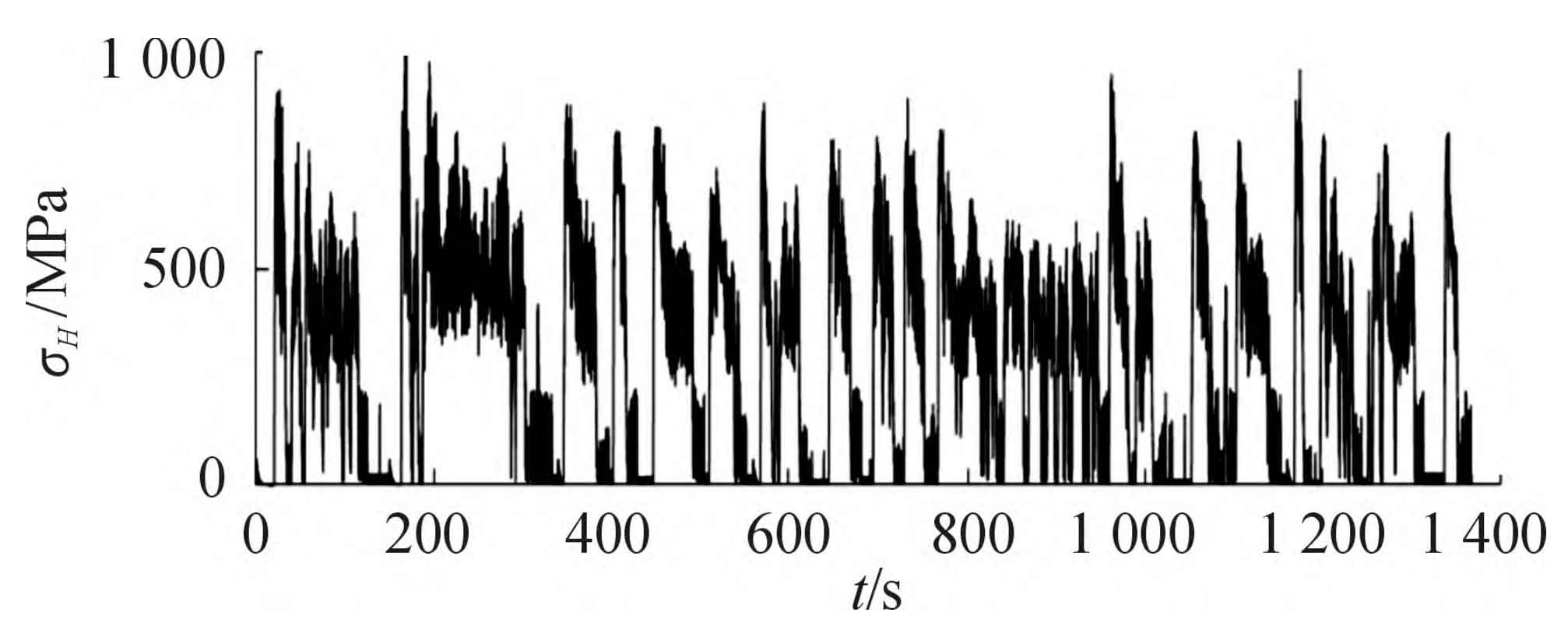
The dynamic torque of the drive motor obtained from the simulation is substituted into the formula, and the contact stress spectrum of the driving gear of the electric vehicle transmission under the cycle condition is calculated based on the quasi-static method, as shown in the figure.