
The S-N curve of the target helical gear is obtained from the S-N curve of the helical gear material, which needs to be corrected according to the formula.
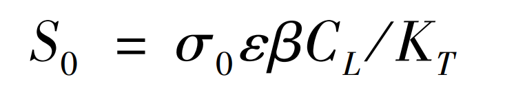
Where: S0 refers to the structural S-N curve stress; σ 0 represents the S-N curve stress of the structural material; KT is the stress concentration factor; ε Indicates the size factor; β Indicates the surface processing coefficient; CL is the loading mode.
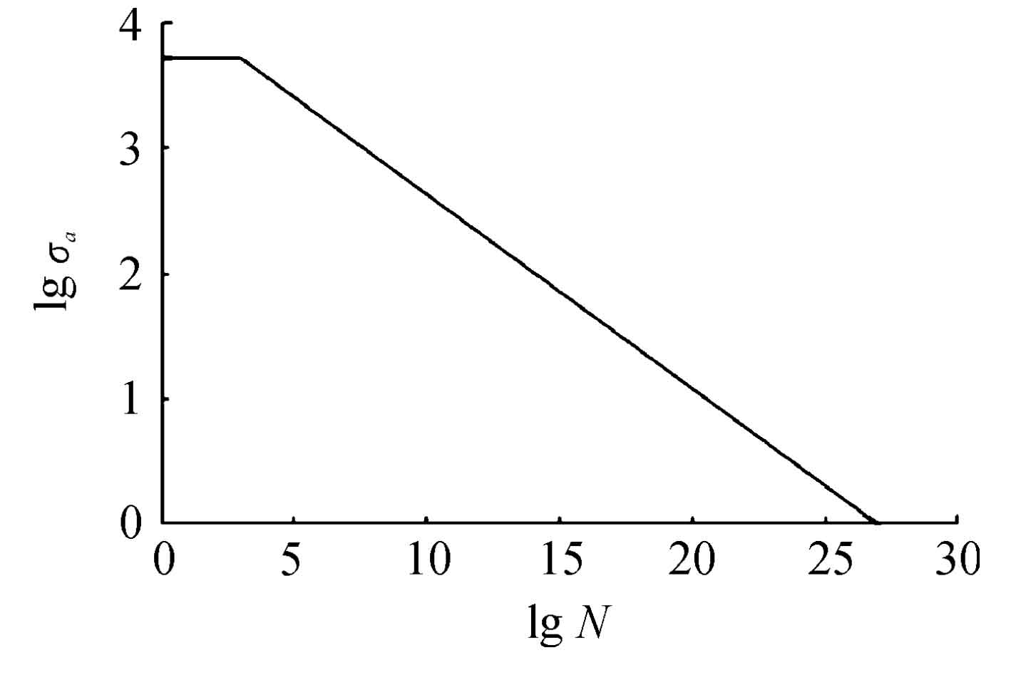
According to experience, the P-S-N curve of the target helical gear material in the Manual of Mechanical Engineering Material Performance Data is modified to obtain the S-N curve of the target helical gear with a survival rate of 99%. The effective stress concentration factor of the selected helical gear material is 1.0, the size factor is 0.86, the surface processing factor is 0.90, and CL=0.85. In addition, because there are many load frequencies that are lower than the fatigue limit in the motor drive system, these loads will also cause cumulative damage to the helical gear, so the EM rule is selected to correct the part of the helical gear P-S-N curve that is lower than the fatigue limit value, that is, the part that is lower than the fatigue limit takes the same slope as the part that is higher than the fatigue limit. So as to obtain σ Under the condition of a, the number of stress cycles to reach fatigue failure, Ni, is shown in Figure 1.
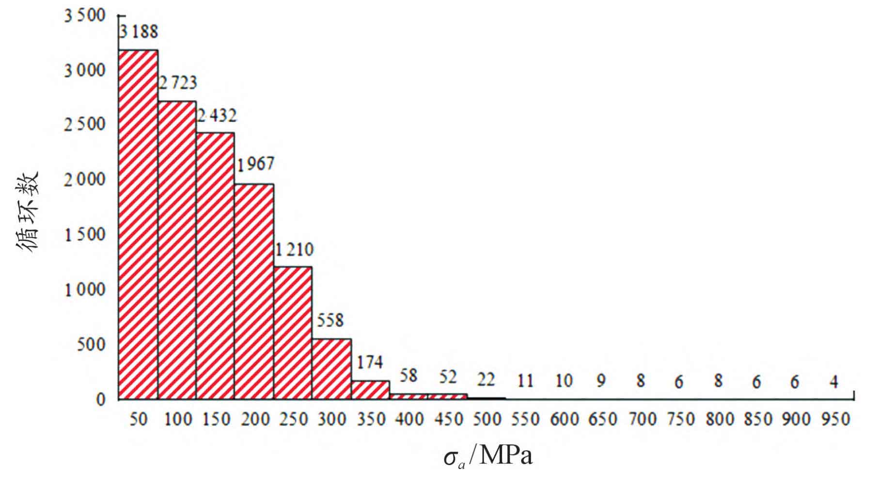
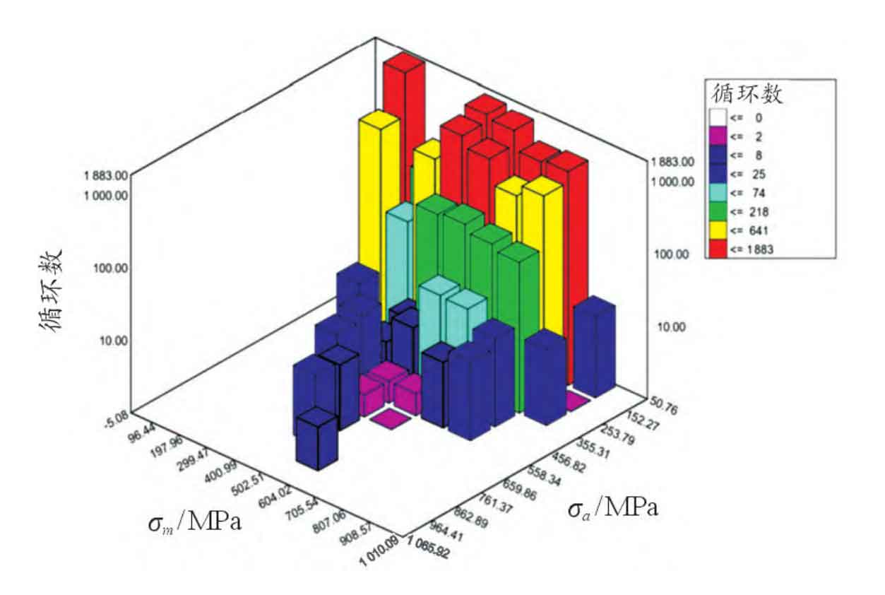
The research shows that the amplitude, mean value and number of cycles of structural stress are the most influential factors on structural fatigue damage. As shown in Figure 2, the mean stress of helical gear contact stress amplitude obtained by rain-flow counting method is not all zero. Therefore, it is necessary to convert the stress cycle of non-zero mean stress into the stress cycle of zero mean stress according to the equivalent damage principle. Generally, the Good ⁃ man fatigue empirical formula can be used to convert it, as shown in the formula. Figure 3 shows the relationship between the amplitude and frequency of contact stress of helical gear at zero average stress.
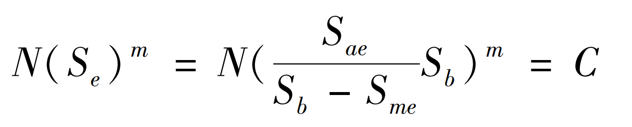
In the formula, Sae and Sme represent the working cycle stress amplitude and average stress calculated by the rain flow counting method; Sb is the strength limit of the component material; Se represents equivalent symmetrical cyclic stress.