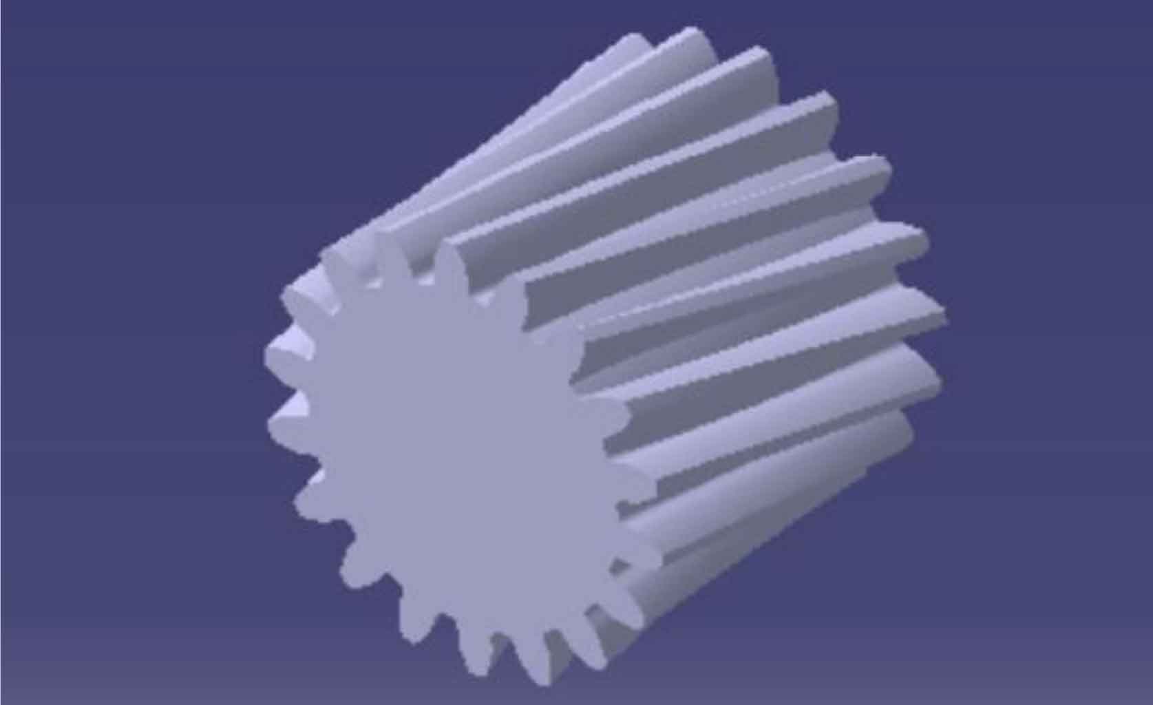
Use the “symmetry” and “rotation” commands of CATIA to draw the gear tooth profile of the other end face of the helical gear, then use the “multi-section surface” command to create the tooth profile surface of a single gear tooth, finally use the “closed surface” command to generate a single tooth entity, and use the array function to generate a complete helical gear entity, as shown in Figure 1.
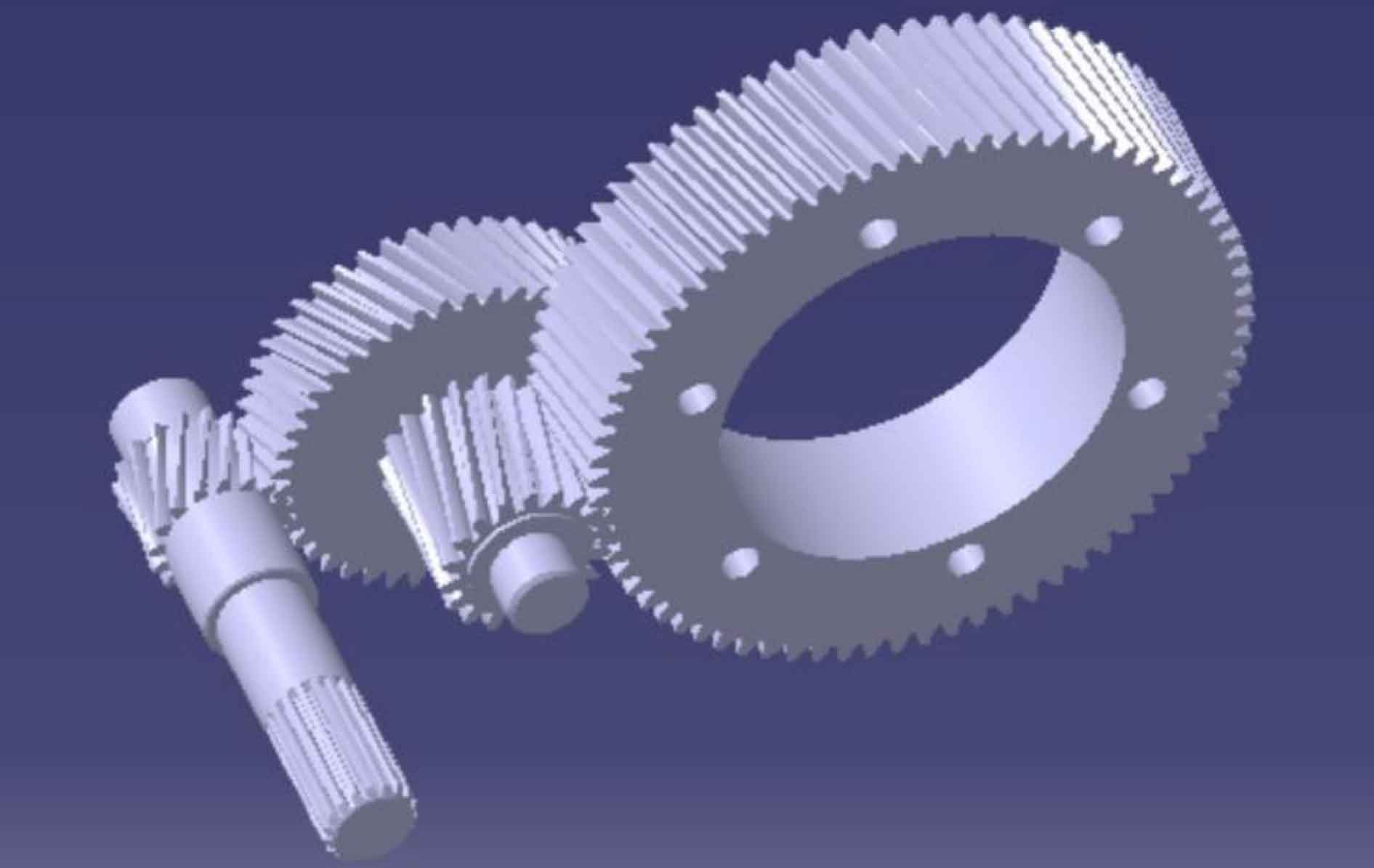
By changing the known basic parameters of the helical gear, the four reduction helical gears of the main reducer can be obtained. In the CATIA assembly design environment, the assembly model of the reduction helical gear of the main reducer is obtained by using the commands of “coincidence” and “offset”, as shown in Figure 2.