
The parameters of a standard helical gear are shown in the table. According to the formula h, the half-width of contact band bg=0.693 7 mm, Hertz contact pressure σ H=997.94 MPa。
| Parameters | Modulus mn/mm | Number of teeth z | Helix angle β/ (°) | Normal tooth angle α n/(°) | Rotation direction | Effective tooth width b/mm | Displacement coefficient xn | Gear addendum height coefficient hap | Tool addendum height coefficient hap0 | Tool fillet coefficient rhoap0 | Input torque T/N · m |
| Helical gear 1 | 6 | 35 | 18 | 20 | L | 70 | 0.2250 | 1 | 1.4 | 0.39 | 8 500 |
| Helical gear 2 | 6 | 85 | 18 | 20 | R | 70 | 0.0238 | 1 | 1.4 | 0.39 | 8 500 |
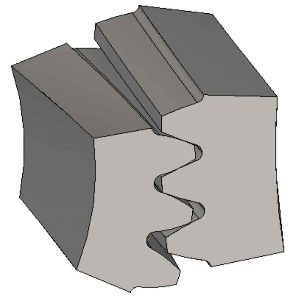
The solid model of helical gear pair under a certain meshing phase is established in ANSYS, as shown in Figure 1. The idea of mesh generation of helical gear pair is as follows: firstly, the end face of helical gear pair is mapped and meshed, and then the mapped end face mesh is scanned along the helix to generate a solid mesh.
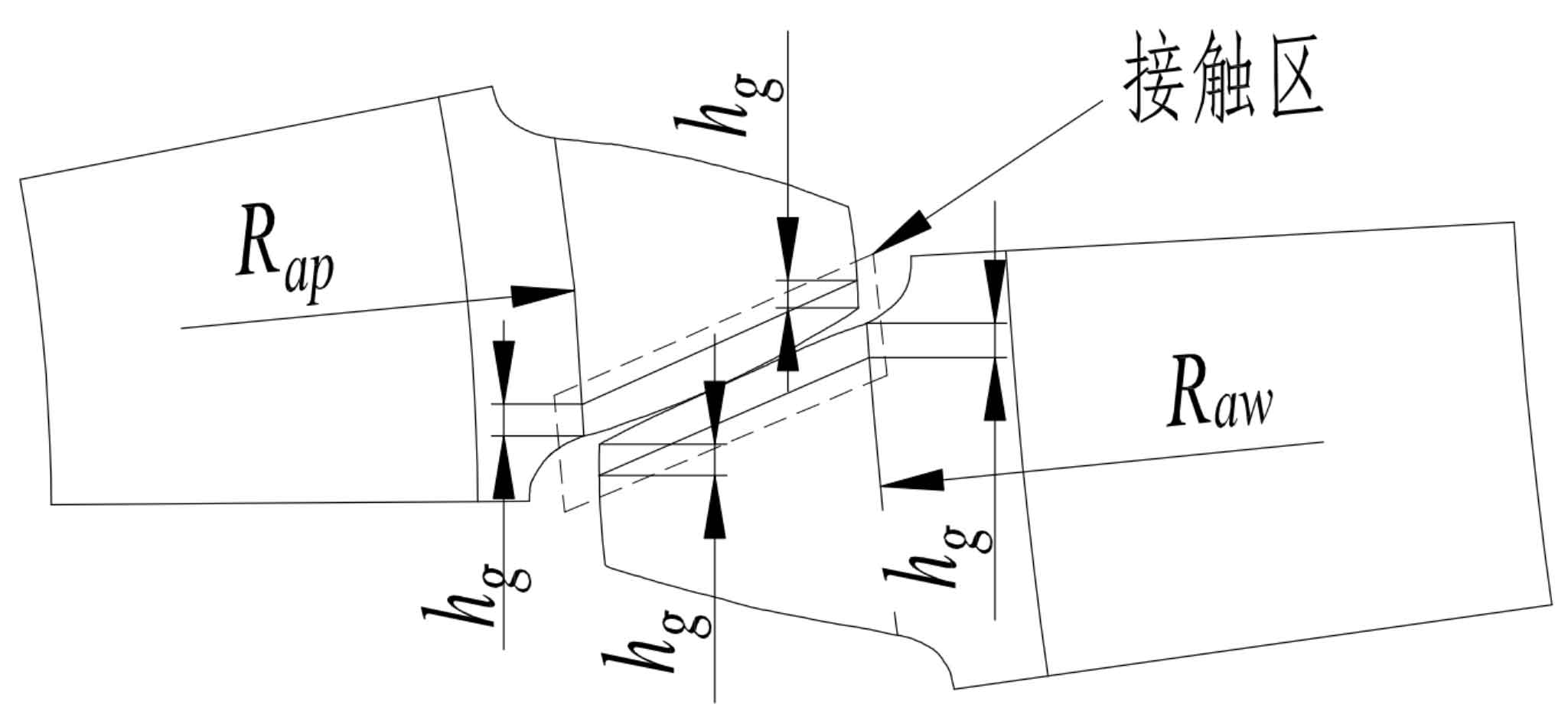
See Figure 2 for the block schematic diagram for the meshing of the single-pair tooth end face mapping of the helical gear pair, where Rap and Raw are the radius of the starting point circle of the involute of the helical gear pair, and hg is the corresponding chord length of the arc used for the contact area planning. In this example, the value is taken as 0.7 mm.
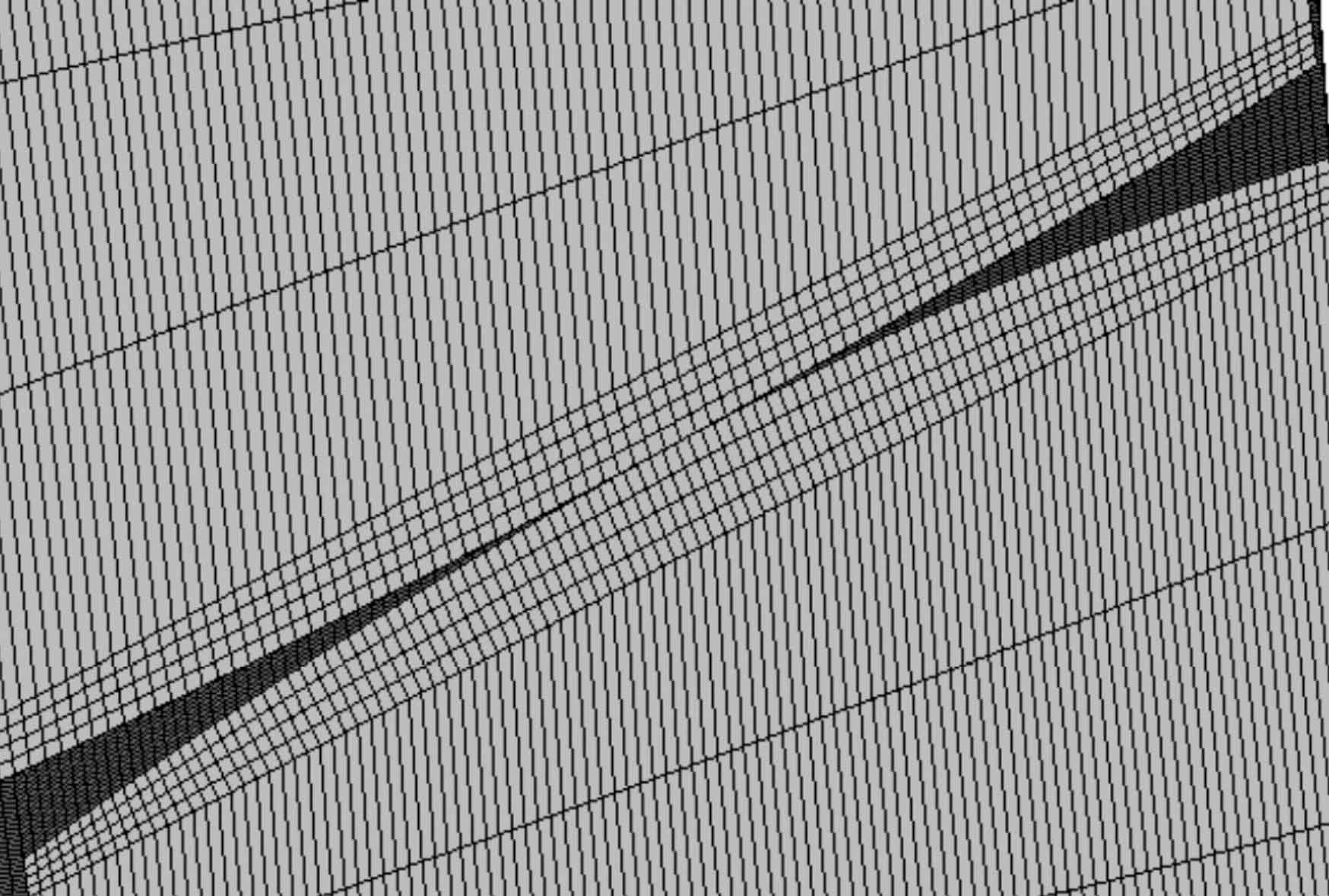
The 8-node SOLID185 element is used to discretize the solid model of the helical gear pair. The mesh of the contact area of a single pair of teeth of the helical gear pair after discretization is shown in Figure 3.
The contact unit adopts CONTA174 and TARGE170, with the pinion as the contact body and the big gear as the target, without considering the tooth surface friction, the contact mode is asymmetric, the normal penalty stiffness coefficient is 1, the penetration tolerance coefficient is 0.1, and the augmented Lagrange method is used to solve. Apply full degree of freedom constraints to all nodes on the internal surface of the big gear, rotate all nodes on the internal surface of the small gear to the cylindrical coordinate system, retain the axial rotation degrees of freedom, constrain the degrees of freedom in other directions, and apply the torque of 8500 N · m equivalent to the circumferential force on each node evenly.
Solve the simulation model, and the contact pressure nephogram of each tooth surface is shown in Figure 4.
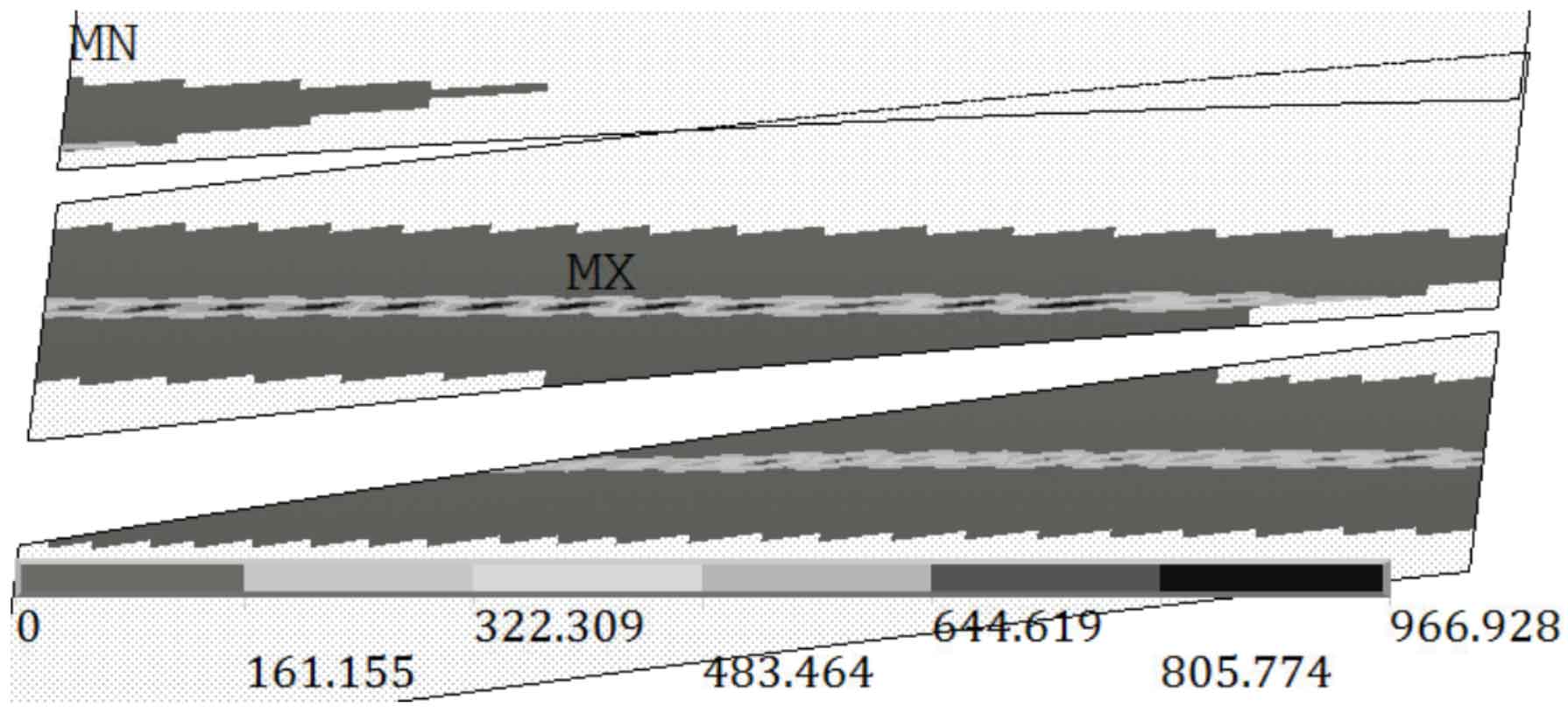
In Figure 4, the maximum contact stress is 966.928 MPa, and the half-width of the contact zone is 0.685 mm. The simulation example shows that the calculated maximum contact pressure is in good agreement with the theoretical value, which shows that the general conclusion that “the mesh size threshold of the contact area is 1/4 times the half width of the contact zone when the mesh independence is verified” is valid in the helical gear contact simulation, The reasonable contact pressure and half-width of contact zone of helical gears can be obtained without grid independence verification.