
The developed model estimates that the tooth profile of spiral bevel gears depends on machining parameters, such as tool inclination and direction, cutting geometry parameters and tool feed and speed values. Two different finishing operations tests were carried out on the model, namely, a 5-axis machining operation and a 3+2-axis machining operation, to determine the impact of the number of machining axes on the surface finish.
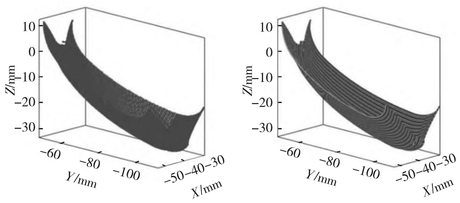
See Figure 1 for the expression of the difference track between the spiral bevel gear teeth. In the first step, obtain the machining program (CL data) for each interpolation point model: the tool tip point position (xj, yj, z) j and the defined tool axis orientation vector (uj, vj, w) j workpiece reference system X, Y, Z. The milling path can be obtained from the coordinates of the continuous tool point. Figure 1-1 shows the position of the tool point obtained by the machining program of the inter-tooth clearance of spiral bevel gears. Figure 1-2 shows the milling path.
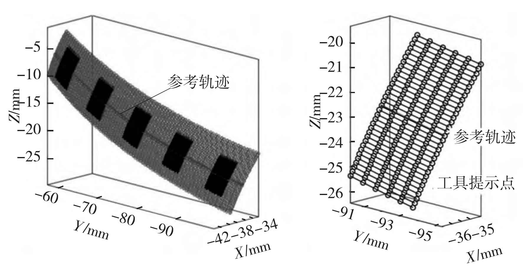
In the next step, after eliminating the initial and final non-cutting motion, evaluate the milling path. As shown in Figure 2-1 on the following page, five simulation areas (black part) are defined in the feed direction. Each simulation area is defined by 6 points in the feeding direction, and there are about 30 points in the direction perpendicular to the feeding direction of spiral bevel gear. The size of the simulation area depends on the programmer’s standard. As an example, Figure 2-2 on the next page shows the tool tip after the milling path in a simulation area considered in Figure 2-1. The black points in each milling path represent the interpolation points given by the machining program of the selected simulation area. Then, the surface topography generated in each simulation area is predicted. To achieve this, a local reference system OWXWYWZW is defined for each simulation area. First, the position of the tool center point (C) in the selected spiral bevel gear simulation area is deduced.