
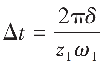
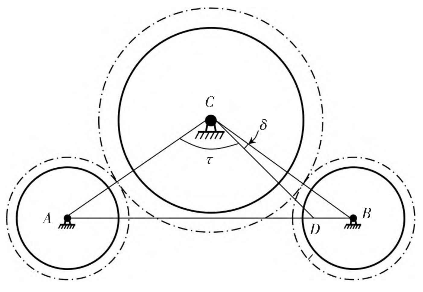
Subject to the layout structure of double-input-single-output gears, as shown in Figure 1, the meshing process of the left and right gear pairs is difficult to fully synchronize, and there is a certain phase difference in the stiffness excitation of both sides. Points A, B and C are fixed supporting points of main and driven gears respectively. In most cases, the number of teeth between ∠ ACB( χ) Is not an integer, will χ Divided into integer parts τ And fractional part δ。 The difference between the stiffness excitation time of the left and right drive gear pairs is:
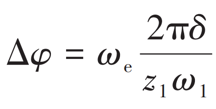
The phase difference can be expressed as:
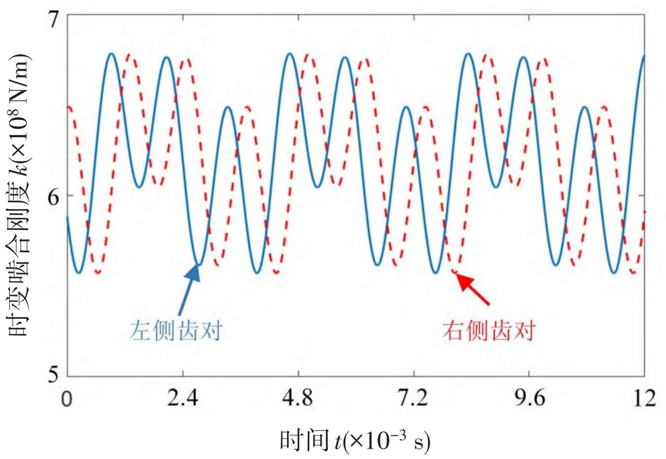
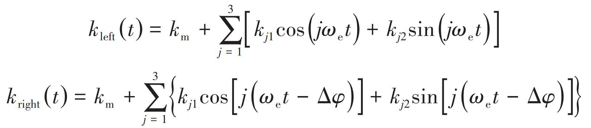
When ∠ ACB=120 ° and the gear parameters are shown in the table, the meshing stiffness of the left and right sides can be obtained by the formula, and the stiffness curve is shown in Figure 2.
| Structural parameters | Driving wheel/driven wheel |
| Number of teeth | 50/100 |
| Modulus/mm | 4 |
| Pressure angle/(°) | 20 |
| Helix angle/(°) | 10 |
| Tooth width/mm | 50 |
| Poisson’s ratio | 0.3 |
| Modulus of elasticity/Pa | 2.06X^11 |
| The overlap ratio | 0.69 |
| Transverse contact ratio | 1.76 |
| Total coincidence | 2.45 |