
Installation error and other factors will change the contact mode of the tooth surface from line contact to point contact. Now we analyze the contact point of the tooth surface, and determine the contact track of the tooth surface with installation error through the contact point of the tooth surface, so as to calculate the tooth surface contact with installation error.
According to the generating motion of spiral bevel gear tooth surface, the tooth surface equation is obtained by coordinate transformation of cutter head cutting path equation. We set the small wheel coordinate system as S1, the big wheel coordinate system as S2, the coordinate system of the rigid fixed connection frame of spiral bevel gear as S3, the cutter head position coordinate system as Qi, the coordinate system of the fixed connection with the cutter head machine tool as Spi, and the coordinate system considering the installation error as Se. According to the meshing principle, the position and direction vector equation of a point M on the cutter head in the coordinate system SQ is as follows:
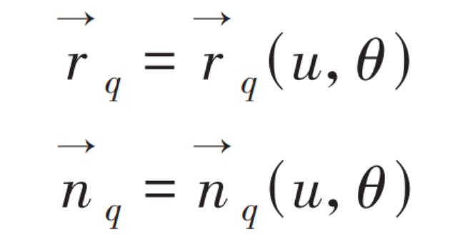
Where: u and θ— Cutterhead motion parameters.
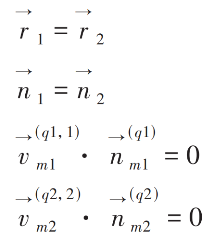
According to the meshing principle of spiral bevel gears, the tooth surface meshing equation can be obtained
The coordinates of spiral bevel gears with installation errors can be obtained by solving the meshing equation of spiral bevel gears with installation errors. On the basis of the three-dimensional model without spiral bevel gears established in the previous article, coordinate adjustment is carried out using UG software, and finally four groups of three-dimensional models of spiral bevel gears with installation errors are obtained. The specific installation error is shown in the table.
| Error type | Offset |
| Axial deviation error of pinion | 0.06mm |
| Axial deviation error of large gear | 0.06mm |
| Axle spacing error | 0.08mm |
| Axis intersection error | 0.05° |