The grinding head drive developed for an iron and steel enterprise uses Gleason spiral bevel gear. First of all, various design parameters of the complex spiral bevel gear must be determined.
It is known that the torque of the input shaft T1=2100 N · m, the big gear is the driving wheel with a rotational speed of 1500 r/min, and the small gear is installed on the main shaft with a rotational speed of 2000~3500 r/min. The reference tooth system parameter is: the normal pressure angle is α N=20 °, addendum height coefficient is h * a=0 85, the coefficient of top clearance is c *=0 188, helix angle β m = 35°。
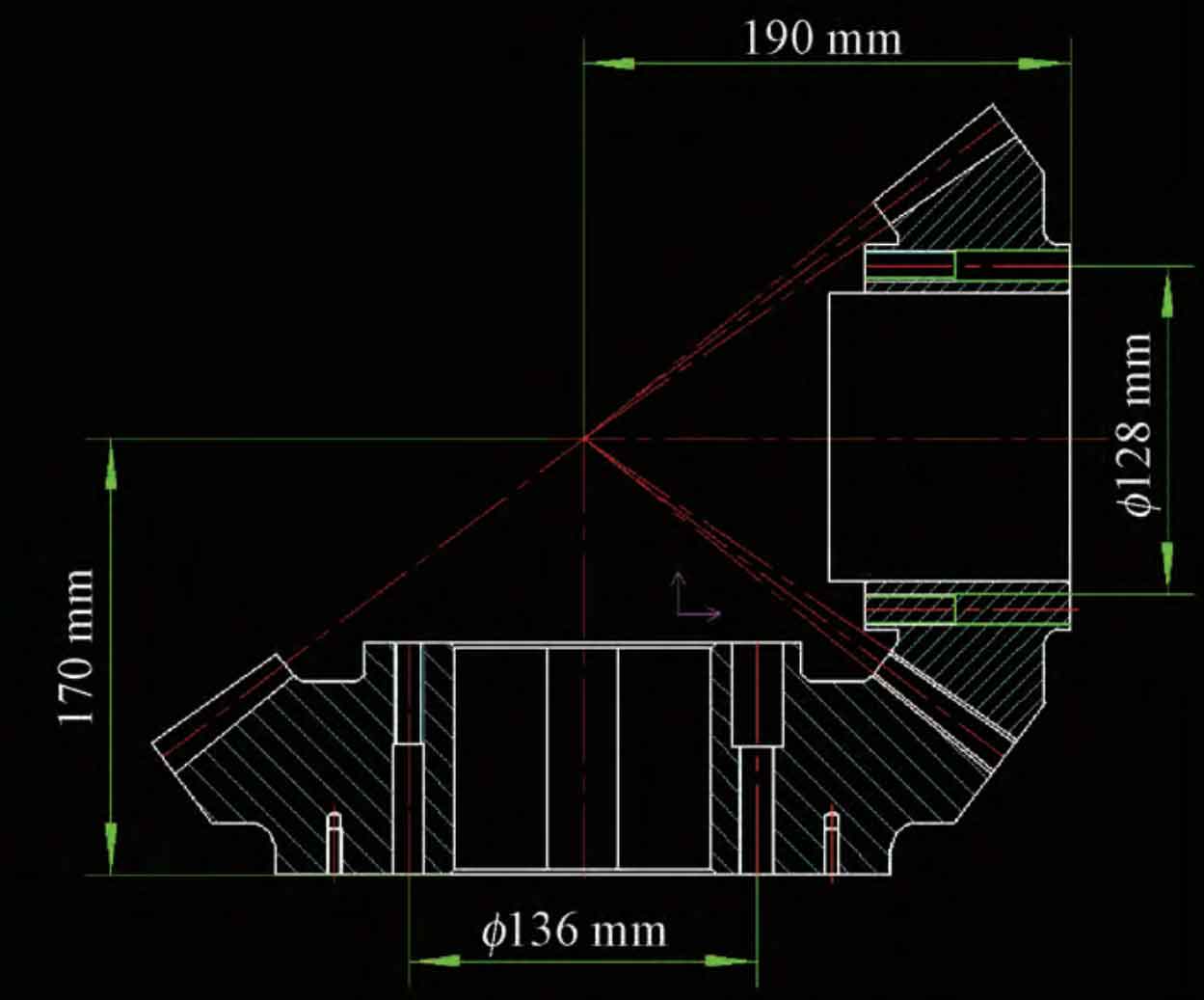
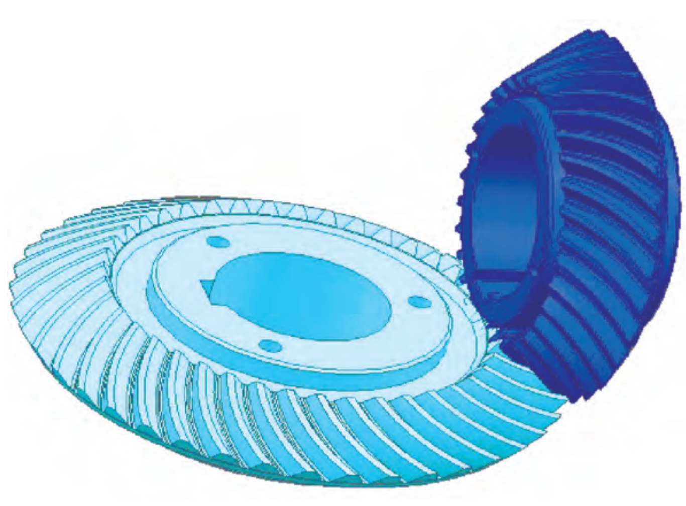
The spiral bevel gear is driven by the motor, and the two wheel shafts intersect Σ = 90 °, the big gear is installed on one end of the input shaft for cantilever support, and the small gear is installed on both ends of the output shaft for bearing support on the box. There are many parameters of spiral bevel gears, which are limited to the length and focus of this paper. The calculation process of parameters is ignored in this paper. The final basic parameters of spiral bevel gears are designed as a two-dimensional diagram (Figure 1). Create a 3D diagram to complete the assembly, as shown in Figure 2.