Because it is difficult to analyze the speed of spiral bevel gear, it is treated as equivalent spur gear. Make the speed analysis diagram of the meshing point of the equivalent spur gear pair as shown in the figure:
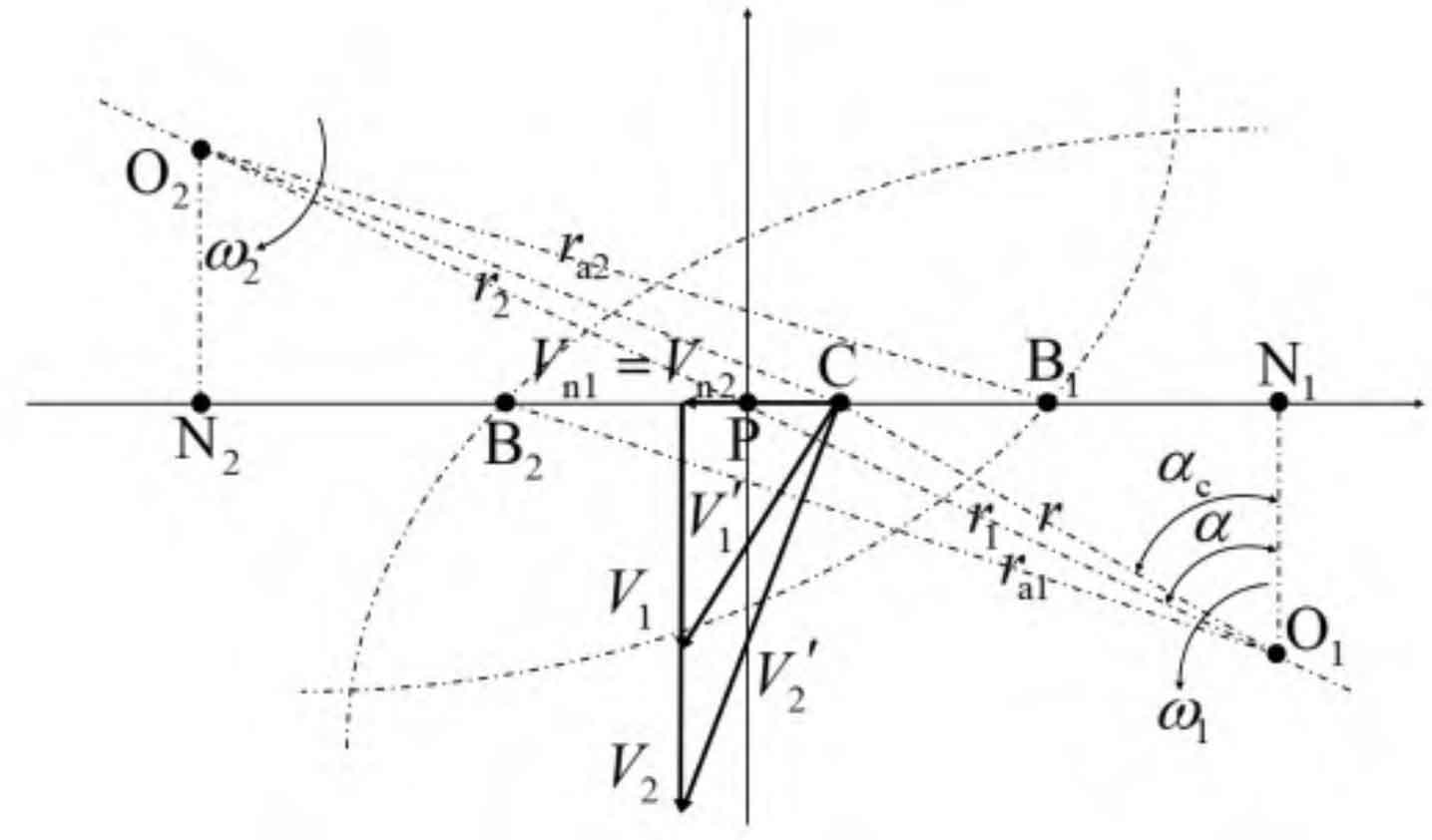
In the figure, P, O1 and O2 are nodes, driving wheel axis and driven wheel axis respectively; R is the distance from the driving wheel axle center O1 to the meshing point C; R1, r2 and ra1, ra2 are the pitch circle radius and addendum circle radius of the main and driven gears respectively; α Is the pitch pressure angle; α C is the pressure angle at engagement point C; N1N2 and B1B2 are theoretical and practical meshing lines respectively.
The speed V ‘of the engagement point C of the driving and driven gears is decomposed along the normal direction (Vn direction in the figure) and the tangential direction (V direction in the figure), and the tangential speed of the driving and driven gears at the engagement point is obtained from the geometric relationship:
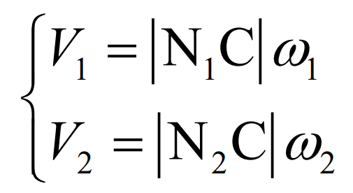
In the formula, N1C and N2C are the line segment distance in the figure.
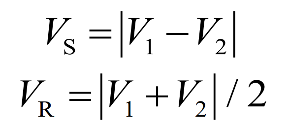
Relative sliding speed VS and entrainment speed VR are respectively: