
The calculation example used is a pair of oil-lubricated spiral bevel gears in a helicopter reducer. See Table 1 for the main parameters.
| Parameter | Value |
| Number of teeth | 27/74 |
| Tooth width/mm | 38.5 |
| Modulus/mm | 3.85 |
| Input speed/(rad/s) | 20900 |
| Input power/kW | 1000 |
| Gear density/(kg/m ^ 3) | 7850 |
| Lubricating oil density/(kg/m ^ 3) | 970.2 |
| Thermal conductivity of gear/(W/m ℃) | 36 |
| Thermal conductivity of lubricating oil/(W/m ℃) | 0.147 |
| Gear specific heat capacity/(J/(kg ℃)) | 641 |
| Specific heat capacity of lubricating oil/(J/(kg ℃)) | 2131 |
According to Zeng Tao’s spiral bevel gear equivalent method, the gear pair is treated equivalently, so that the tooth parameters at the midpoint of the tooth width of the equivalent straight cylindrical gear pair and spiral bevel gear are the same.
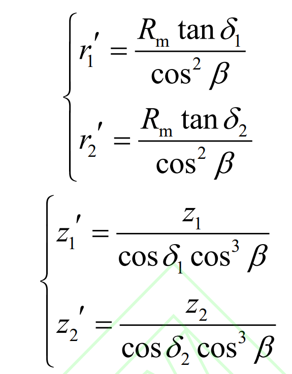
Where, r ‘and Rm are the pitch radius of the equivalent straight cylindrical gear and the taper distance of the spiral bevel gear; Z ‘and z are the number of teeth of equivalent straight cylindrical gear and spiral bevel gear respectively; δ 、 β They are taper angle and helix angle of spiral bevel gear.
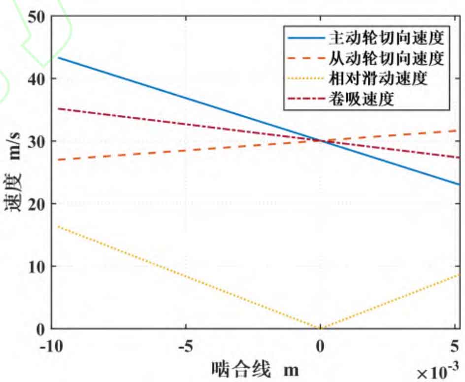
Keep the linear speed of the indexing circle of the equivalent straight cylindrical gear the same as the linear speed of the indexing circle of the midpoint of the tooth width of the spiral bevel gear, draw the speed analysis diagram of the meshing point of the equivalent straight cylindrical gear according to the true scale, and calculate the instantaneous speed of each point in the meshing area by the formula, as shown in Figure 1.
According to the research of Wang Wei and others, the highest point of tooth surface temperature of spiral bevel gear is the midpoint of tooth width. Since the Joseito flash temperature method is only applicable to the node where the maximum temperature rise is estimated, in order to facilitate comparative analysis, this paper only calculates the flash temperature of the node at the midpoint of the tooth width.
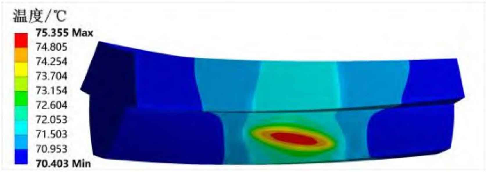
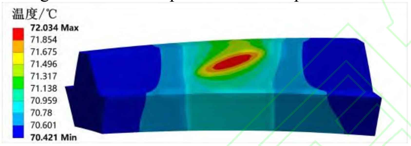
Under the input power of 1000kW, the convective heat transfer coefficient of each surface of spiral bevel gear tooth is calculated by the formula, and then the instantaneous heat generation and average heat generation at the midpoint of the width of the driving and driven gear teeth are calculated by combining the instantaneous speed diagram and the formula. Load it into the simulation software and calculate the body temperature and transient temperature nephogram at the midpoint of the tooth width of the driving and driven gears, as shown in Figures 2 to 5.
Then, the improved Blok flash temperature method and Joseito flash temperature method are used to calculate the tooth surface flash temperature through the formula. The calculation results of the three methods are shown in Table 2.
| Method | Main and driven gear tooth body temperature/℃ | Flash temperature of driving and driven gear teeth/℃ | Maximum temperature of driving and driven gear teeth/℃ |
| Improved Blok flash temperature method | 75.36/72.03 | 19.11/18.41 | 94.47/90.44 |
| Joseito flash temperature method | 75.36/72.03 | 26.62/27.97 | 101.98/100.00 |
| Finite element simulation method | 75.36/72.03 | 15.28/19.56 | 90.64/91.59 |
When the input power is 800kW and 1200kW, the above three methods are used to calculate and draw the tooth surface flash temperature histogram under different input power as shown in Figure 6 and Figure 7.
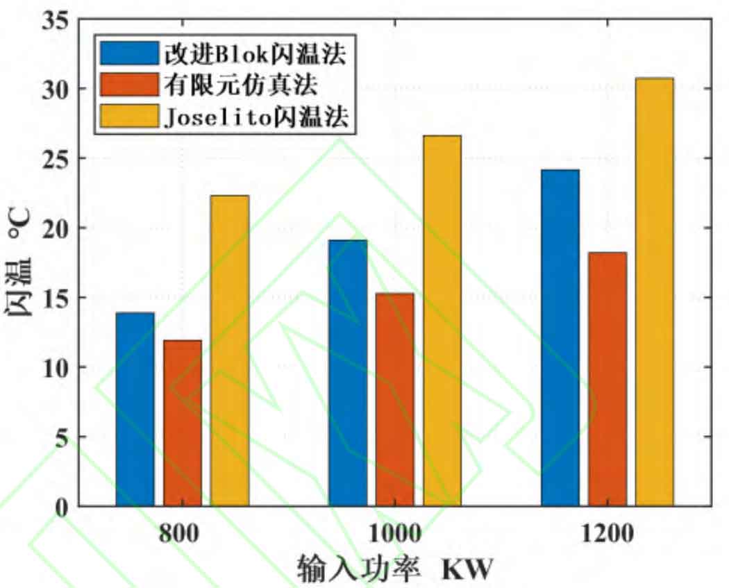
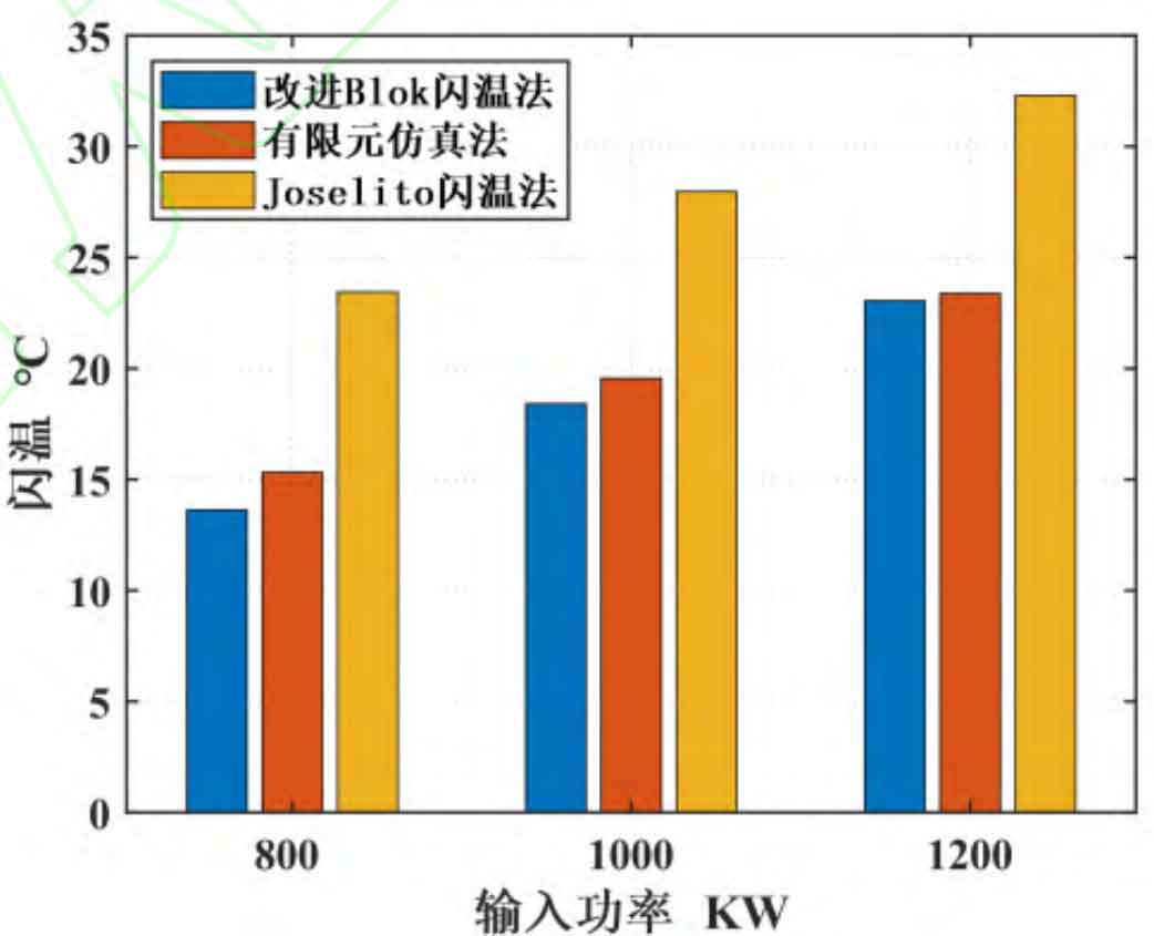
From the point of view of the scuffing resistance of the spiral bevel gear teeth, more attention is generally paid to the highest temperature on the spiral bevel gear teeth. It can be seen from Table 2 that on the basis of the calculation results of the finite element simulation method, the maximum temperature of the Joseito flash temperature method is about 12% higher than that of the improved Blok flash temperature method, while the maximum temperature of the improved Blok flash temperature method is about 4% higher, which shows that the numerical solution of the improved Blok flash temperature method is closer to the results of the finite element simulation. Since the finite element simulation method is more widely used than the Joseito flash temperature method, it can be temporarily considered that the calculation accuracy of the improved Blok flash temperature method is better than that of the Joseito flash temperature method, which will be verified by experiments in subsequent studies. There are many factors that affect the flash temperature of the tooth surface. To test the stability of the algorithm, the control variable method is used to observe the change of the flash temperature calculation results by changing the input power and replacing different types of lubricating oil.