
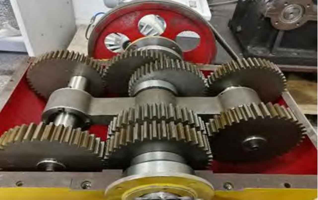
The main idea of the meshing line increment method is to equivalent the center distance error and eccentricity error to the instantaneous meshing line of non-circular gears, and convert the increment of the meshing line of the driving wheel and the driven wheel under different steering to the angle of the driven wheel, then the transmission error of the driving wheel under different steering can be obtained. In the commutation device of the non-circular gear pumping unit (Fig. 1), the non-circular gear pair needs frequent positive and reverse movements to realize the reciprocating movement of the sucker rod. In this process, due to the difference between the bidirectional transmission errors and the existence of the backlash between the teeth, the input shaft and the output shaft will be out of contact in a short time, resulting in sudden interruption of output and intermittent “beating” phenomenon, This will lead to the nonlinear change of the transmission relationship, which will have a certain impact on the dynamic performance of the pumping unit. Therefore, it is necessary to establish the non-circular gear bidirectional transmission error model.
b Driven wheel mesh line increment
b Driven wheel mesh line increment
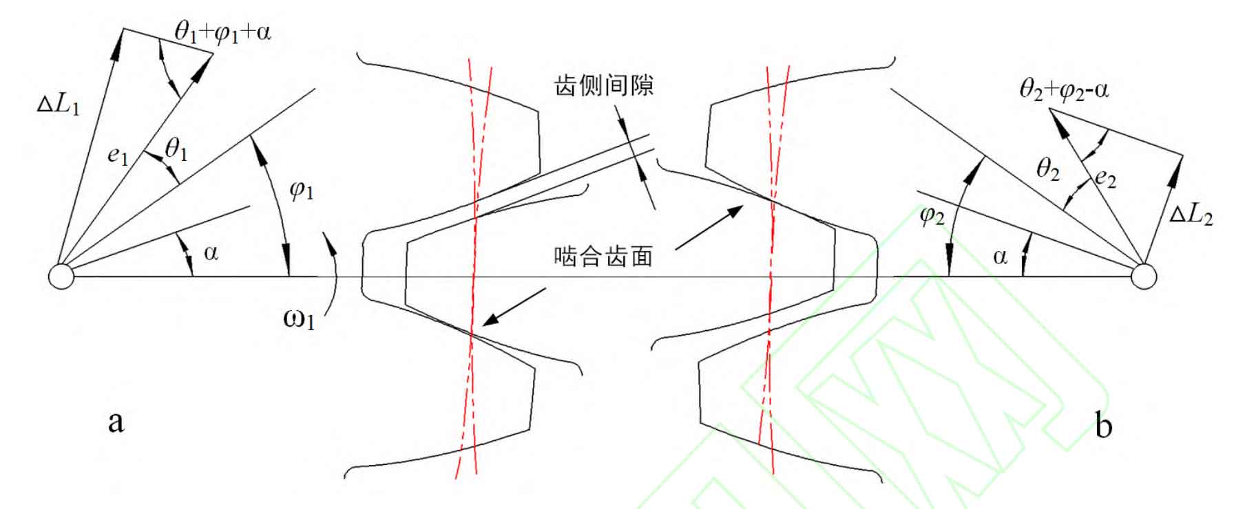
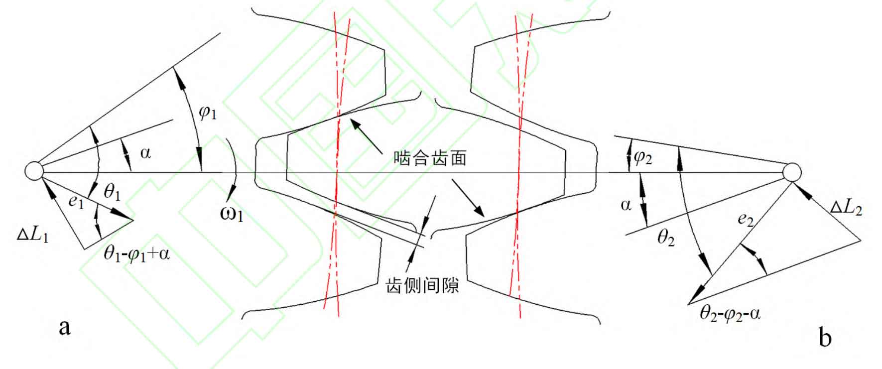
Figure 2 and Figure 3 are the calculation diagrams of meshing line increment when the driving wheel rotates counterclockwise and clockwise. In the figure, e1 and e2 are eccentric errors of main and driven wheels respectively; θ 1 and θ 2. Main and driven wheel corners; φ 1 and φ 2. Initial phase of main and driven wheels; Δ L1 and Δ L2 is the increment of meshing line of main and driven wheels respectively; α Is the pressure angle at the node.
Combined with Figure 2 and Figure 3, it can be obtained that the mesh line increments of the driving wheel and the driven wheel are respectively (+counterclockwise rotation of the driving wheel, – clockwise rotation of the driving wheel):
At the initial moment, the meshing line increment caused by eccentric error is:
Based on the meshing line increment method, the transmission error of the driving wheel when it rotates counterclockwise and clockwise can be obtained as follows:
In the above formula, rb=rcos α , Rb is the base circle radius of non-circular gear, r is the pitch curve radius of non-circular gear, α Is the pressure angle at the pitch circle of non-circular gear.
The backlash of non-circular gears mainly includes constant backlash and periodic time-varying backlash. The constant backlash is mainly composed of tooth thickness deviation and center distance error. The periodic time-varying backlash is caused by the eccentric error caused by the manufacturing and assembly of bearings, shafts and gears. It is pointed out that the total backlash of non-circular gear pair with eccentric error can be obtained by the transmission error under two-way no-load. Therefore, the periodic backlash of non-circular gear pair can be expressed as:
Where α Is the center distance of non-circular gear pair.
because α>> e1, α>> E2, so the formula can be simplified as: