In order to turn the entire tooth surface of the face gear when turning the face gear with a conical gear turning tool Σ 2. The gear turning tool needs to make two relatively independent motions relative to the face gear: the generating motion between the turning tool and the workpiece and the feed motion of the turning tool along the axis of the generating wheel.
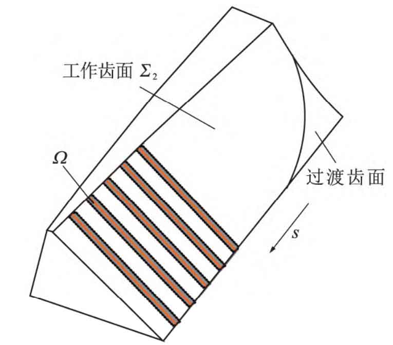
The generating motion is the angular velocity of helical gear around its own axis z2 ω 2 Rotate, while the turning tool rotates around its axis zs at angular speed ω S rotation, the rotation of the face gear and the rotation of the gear turning tool constitute the generating motion of the spiral tooth face gear in the process of gear turning. Because the cutting edge curve of the tool is in point contact with the workpiece, the cutting edge is on the tooth surface of the workpiece in one meshing cycle Σ 2 Envelope a narrow band area Ω (see Figure 2). In order to turn the entire tooth surface, after turning the gear turning tool for one meshing cycle, its center Os needs to translate the distance s along the axis zg of the virtual generation wheel, which constitutes the feed motion in the gear turning. Therefore, the process of machining helical gear is the process of turning the gear cutter for one meshing cycle and moving the tool center once until the whole gear surface is cut.
When the feed motion of the turning tool along the radial direction of the helical gear is not considered, the rotation relationship between the helical gear and the turning tool is:
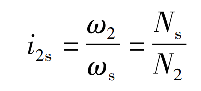
Where, N2 is the number of teeth of helical gear; Ns is the number of teeth of the gear turning tool.
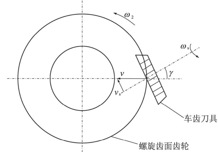
During actual machining, the machining of the entire tooth width can only be completed through the continuous feed of the gear turning tool along the radial direction of the helical gear. Figure 3 is the projection diagram of a certain cutting point perpendicular to the axial direction of the helical gear. The feed speed of the tool has a velocity component vs along the normal direction of the helical gear tooth line, which is equivalent to the original rotation speed of the gear turning tool ω An additional speed is added on the basis of s Δω s. Its direction is the same as ω S is the same, the size is:
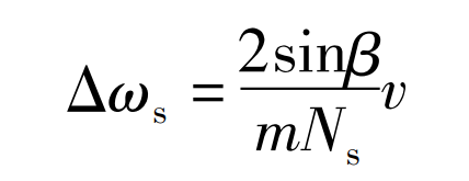
Where, v is the feed speed of the turning tool along the radial direction of the helical gear; β Is the helical angle of the imaginary generating wheel corresponding to the helical gear; M is the modulus of the straight tooth turning tool.
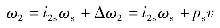
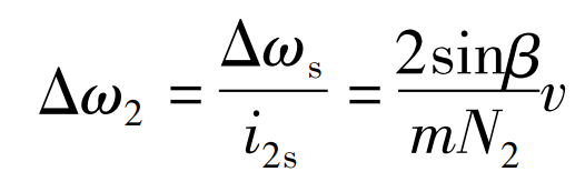
The rotation speed increment affects the original correct meshing of the turning tool and the helical gear. The rotation speed increment of the turning tool can be offset by adding a rotation speed to the original rotation of the turning tool or the helical gear Δω s. So as to ensure the correct tooth profile of helical gear. If the additional speed is passed through the tool, the direction of the additional speed should be opposite to the direction of the speed increment, i.e Δω S takes a minus sign; If additional speed is added through helical gear, the direction of additional speed shall be the same as the direction of speed increment, i.e Δω 2 Take the positive sign. The additional speed of helical gear is:
Ps=2sin β / MN2, the formula can be expressed as:
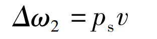
At this time, the speed of helical gear is: