The accuracy of the dynamic model of the straight bevel gear transmission system is affected by the accuracy of the time-varying parameter calculation model. Because the tooth profile of straight bevel gear is relatively complex, the existing research has simplified the calculation of its time-varying parameters. Based on the meshing principle of straight bevel gears, this paper uses the finite element method to establish a time-varying parameter calculation model.

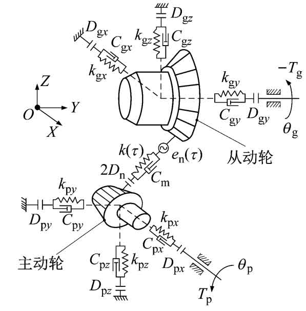
The simplified physical model of straight bevel gear transmission system considering backlash and bearing support is shown in Figure 1. P and g represent the driving wheel and driven wheel respectively. The base circle radius of the equivalent straight bevel gear is Rbj, and the torsional vibration displacement is θ J. Inertia moment is Ij, torque is Tj, k( τ) Is the time-varying meshing stiffness, and Cm is the meshing damping coefficient. en ( τ) Is the comprehensive transmission error along the direction of the meshing line. 2Dn is the tooth side clearance, kjl, Cjl and Djl are the bearing support stiffness, bearing support damping coefficient and bearing clearance along the l direction respectively. Where j=p, g and l=X, Y, Z.
| System parameters | Driving wheel | Driven wheel |
| Modulus/mm | 4 | 4 |
| Number of teeth | 10 | 16 |
| Pressure angle / (°) | 25 | 25 |
| Tooth width/mm | 10 | 10 |
| Pitch cone angle/(°) | 32.0054 | 57.9946 |
| Coincidence degree | 1.353 | 1.353 |
| Outer taper distance/mm | 37.736 | 37.736 |
| Axis intersection angle/(°) | 90 | 90 |
| Addendum coefficient | 1.0 | 1.0 |
| Young’s modulus/(N · mm ^ – 2) | 206 | 206 |
| Poisson’s ratio | 0.3 | 0.3 |
The table shows the system parameters of the straight bevel gear transmission part in a certain automobile differential. The fit degree is 1.353. Combined with the influence of backlash, there are five meshing states in the straight bevel gear transmission, such as single/double tooth surface meshing, gear tooth disengagement, and single/double tooth back contact.
Set δ P and δ G is the pitch cone angle of the main and driven gears respectively, Xj, Yj and Zj (j=p, g) are the vibration displacement of the two gears along the X, Y and Z directions respectively, α N is the pressure angle of the two gears, Fn and Ff are the positive pressure and friction on the meshing point, Fnl and Ffl (l=X, Y, Z) are their components along the l direction respectively, then the relative displacement of the straight bevel gear pair along the normal direction of the meshing point is shown in the formula.
The positive pressure Fn and friction Fnl at the meshing point of the straight bevel gear and their components can be obtained from the formula.
