
After image segmentation, the grinding crack image of an automobile gear becomes optimized data that can accurately extract regional features. Based on the image contour recognition technology of two-dimensional laser radar point clouds, the shape features, density features, and area features of the grinding crack image are extracted from multiple angles such as the longitudinal and transverse directions, to achieve the extraction of the overall features of the automotive gear damage image.
1. Shape characteristics
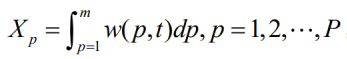
The shape features of the grinding crack image are calculated by projecting horizontally and vertically within the three pixel threshold regions and relying on the projection coordinates.
Set the horizontal projection coordinates as:
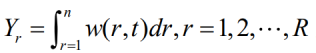
The vertical projection coordinates are:
The formula for calculating the shape characteristics of the grinding crack image is as follows:
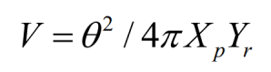
Where: V is the shape perimeter of the damaged image; θ Is a broken image parameter.
2. Density characteristics
Density factor is a non-stationary filter operator with a frequency limit of d, which is commonly used to identify the density characteristics of images. Add non-stationary filter operators with the same limit to the three pixel threshold regions, and observe the distance between the automotive gear grinding crack image and the pixel value center position after being affected by the non-stationary filter operator. The closer the distance is, the closer the gray value of the image approaches 1, and the farther the distance is, the closer the gray value of the image approaches 0. By inputting the comparison results into the convolution operation model, the density characteristics of the grinding crack images of automotive gears can be obtained. The expression of the non-stationary filter operator is as follows:
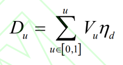
Where: η Is the filtering constant; U is the frequency limit of the non-stationary filter operator.
3. Area characteristics
To calculate the area of a unit automotive gear grinding crack image within the three pixel threshold regions, it is necessary to first lock the image boundaries, gradually expand by relying on boundary elements, until the entire image is surrounded, and obtain the area characteristics of the automotive gear grinding crack image. The calculation expression for locking the broken image boundary is as follows:
Where: L ^ o is the boundary parameter.
Using all the above formulas to complete the feature extraction of automotive gear grinding crack images is conducive to subsequent image recognition of automotive gear grinding cracks, greatly improving the accuracy and effectiveness of image recognition.