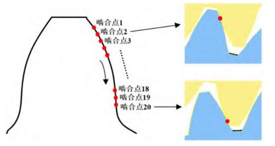
In order to study the impact of different center distance deviations on the stiffness of a gear tooth during a meshing cycle, the meshing process of a single gear tooth including the center distance deviation is discretized into 20 meshing points, as shown in Figure 1. Taking 20 meshing points as a meshing cycle, the static transmission error and meshing stiffness at each meshing point are calculated, and the static transmission error curve and time-varying meshing stiffness curve of the spur gear are obtained through fitting.
The models of spur gear pairs at different meshing points are established under the conditions that the center distance deviations are 0 mm, 0.06 mm, and 0.12 mm, respectively. The studied spur gear parameters are shown in the table. A three-dimensional geometric model of the spur gear pair including center distance deviation is established in the professional spur gear design software Kissoft.
| Parameters | Parameter value of driving wheel | Parameter value of driven wheel |
| Number of teeth | 31 | 36 |
| Modulus | 3 | 3 |
| Tooth width/mm | 12 | 12 |
| Pressure angle/(°) | 25 | 25 |
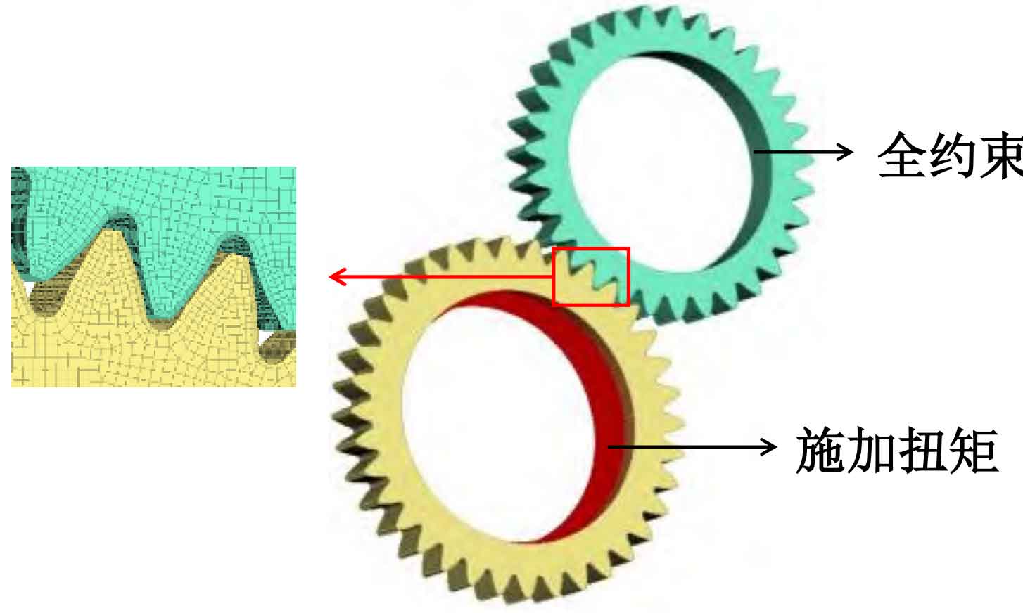
Import the 3D model into ANSA finite element preprocessing software to establish a static meshing finite element model of involute spur gear pairs including center distance error, as shown in Figure 2. When applying boundary conditions to the spur gear pair model, a rigid body shell is attached to the inner ring of the spur gear, where the rigid body shell of the driven wheel constrains all degrees of freedom except for the degrees of freedom of axial rotation, while the rigid body shell of the driving wheel is fully constrained. In addition, in order to eliminate the impact of initial backlash, a small torque of 0.1N · m is applied from the inner ring of the moving wheel starting from 0s, and gradually increases after 0.005s. When it reaches 0.025s, the torque reaches the maximum value, with a size of 200N · m, and maintains until 0.03s. Finally, apply contact between the contact tooth surfaces of the driving and driven wheels, output the model in the format of a key file, and import it into LS-DYNA for solution.