
Convert the cylindrical gear pair established by UG to X_ T intermediate format, and then import it into the dynamics simulation software Adams. Finally, add some settings in Adams, as follows:
(1) Units. Choosing a reasonable unit is the key to modeling, and is also a prerequisite to ensure that the correct analysis results are obtained. The unit system selects millimeters, kilograms, and seconds (MMKS).
(2) Modify the mass characteristic parameters of cylindrical gear pairs. The material of the cylindrical gear pair is a 20CrMnTi rigid body, and the parameters are modified according to the actual material.
(3) Set the rotation pair. Set the rotation Marker points at the rotation centers of the two cylindrical gears, so that both cylindrical gears rotate relative to the ground.
(4) Establish contact. Establish an impact contact between cylindrical gear pairs, input the meshing stiffness coefficient K and the meshing damping coefficient C, whose values are calculated to simulate the actual contact situation when the cylindrical gear pair rotates.
(5) Establish an input source. Add a STEP function to the input cylindrical gear to keep its rotational speed at 0 Increase from 0 to 154 rad/s (1470 r/min) within 1 s, i.e. step (time, 0 s, 0 rad/s, 0 1 s,154 rad/s)。
(6) Establish load torque. Add a load torque to the output gear to keep its torque at 0 Increase from 0 to 150 N · m within 1 s, i.e. step (time, 0 s, 0 N · m, 0 1 s,-150 N·m)。
(7) Model constraint checking. Use the model verify command in tools to view the overall constraint information of the model.
(8) Simulation. Using simulation, set the simulation time to 0 5 seconds, set the step size to 4500 steps, use a dynamic integration module, select GSTIFF and SI2 integration solvers, and perform simulation analysis after completing the settings.
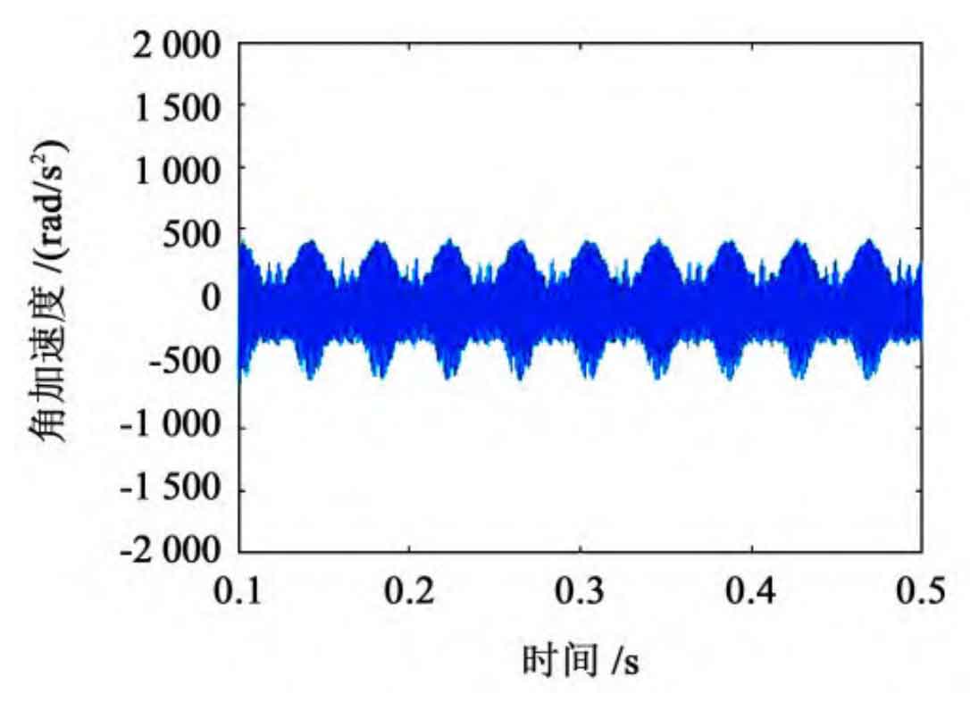
Figure 1 shows an output cylindrical gear angular acceleration image of the original structure, indicating that the cylindrical gear is at 0 After 1 s acceleration and load excitation, the vibration tends to stabilize.
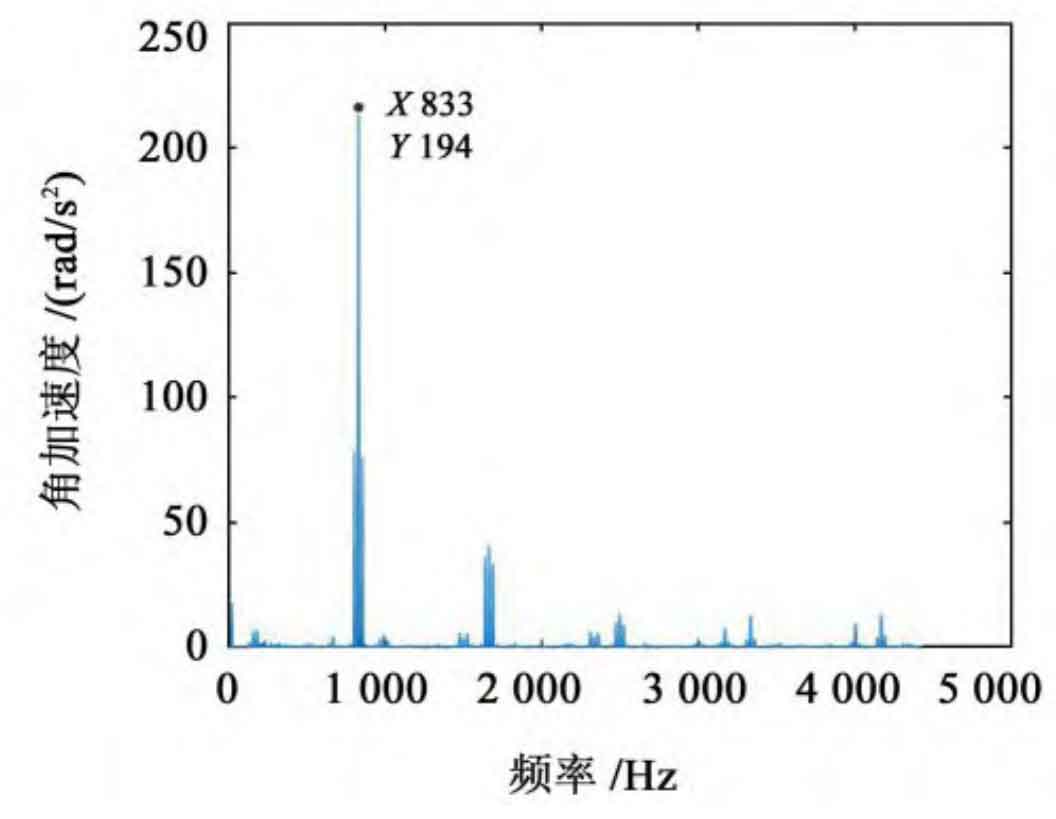
Convert the angular acceleration under the time domain diagram of the output cylindrical gear into a spectrum diagram through Fourier transform, as shown in Figure 2. It can be obtained that the angular acceleration amplitude at the meshing frequency of 833 Hz is 194 rad/s2.