
The angular acceleration amplitude at the meshing frequency is taken as the evaluation index of the system, and the angular acceleration of 9 pairs of cylindrical spur gear pairs is analyzed as the dependent variable.
1. Range analysis
The comprehensive average value of each factor at each level can be calculated through the data, and the calculation results are shown in Table . In Table , Ti represents the average value of each evaluation index for the level of i under a certain factor, and S represents the range of Ti for a certain factor, that is, S=max (T) i-min (T).
| Parameter (/rad/s^2) | A(a1) | B(a2) | C(a3) |
| T(1 a) | 186 | 212 | 178 |
| T(2 a) | 188 | 185 | 186 |
| T(3 a) | 187 | 164 | 197 |
| S(a) | 2 | 48 | 19 |
To visually represent the influence rule and trend of various factors on angular acceleration, Figure 1 is drawn with the factor level as the abscissa and the angular acceleration amplitude as the ordinate.
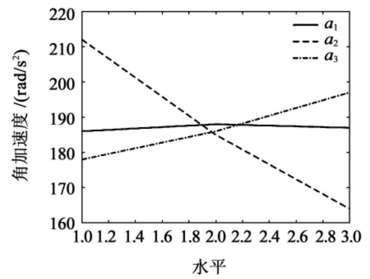
From Figure 1, it can be seen that the groove width a1 has little influence on the angular acceleration amplitude, and the influence of the side gap a2 is much greater than the influence of the small hole diameter a3.
2. Signal to Noise Ratio Analysis
The signal to noise ratio can measure the fluctuation of the index. For the evaluation index of angular acceleration, it is expected to be small, that is, the smaller the amplitude of angular velocity, the better, indicating that the vibration of cylindrical spur gear pairs during meshing is also smaller. For desired small characteristic indicators, the signal-to-noise ratio is defined as:
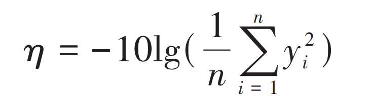
In the formula, n is the number of repeated tests; Yi is the ith test value.
Calculate the horizontal signal-to-noise ratio of each factor, using the test factor level as the abscissa and the nominal signal-to-noise ratio as the ordinate to draw Figure 2. From the range of the three factors shown in Figure 2, it can be seen that the primary and secondary order of the influence of the three factors on the amplitude of diagonal acceleration is B>C>A, which is consistent with the range analysis,
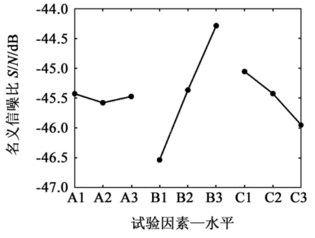
The closer the signal to noise ratio is to 0, the smaller the angular acceleration evaluation index is. Therefore, as can be seen from the figure, the optimal combination is A1B3C1, i.e., the groove width is 0 2 mm with a side gap of – 0 03 mm, with a small hole diameter of 4 mm.