| Gear | Number of teeth z | Modulus m/mm | Modification coefficient x | pressure angle α (/ °) | Tooth top height coefficient hα* | Top clearance coefficient c* | Tooth width b/mm |
| z1 | 34 | 6 | 0.394 5 | 20 | 1 | 0.25 | 60 |
| z2 | 34 | 6 | 0.394 5 | 20 | 1 | 0.25 | 60 |
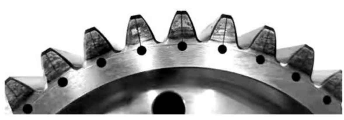
Based on the spur gear parameters and orthogonal test simulation results in Table 1, four types of spur gears with common normal length were designed to verify different meshing backlash, one of which was provided with a vibration reduction slot hole. The measured common normal length of spur gears after gear grinding is shown in Table 7. The spur gear C is provided with a vibration damping slot hole at the gear tooth, and its substance is shown in Figure 1.
According to the test of matching 4 spur gears with 3 groups as shown in Table 2: ① Side clearance of A-B spur gear pair is 0 2 mm;② B-C spur gear pair side clearance 0 07 mm;③ The side clearance of the C-D spur gear pair is – 0.03 mm.
| Spur gear number | Length of common normal/mm | Whether vibration damping structure | Input/Output |
| A | 84.075 | No | Input |
| B | 84.101 | No | Output |
| C | 84.192 | Yes | Input |
| D | 84.199 | No | Output |
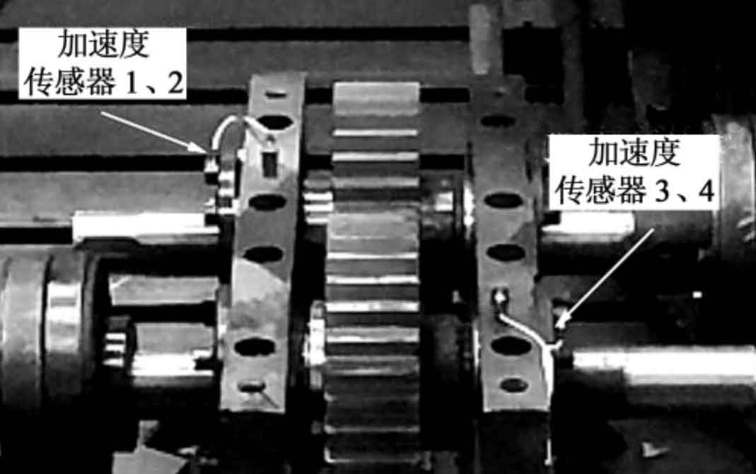
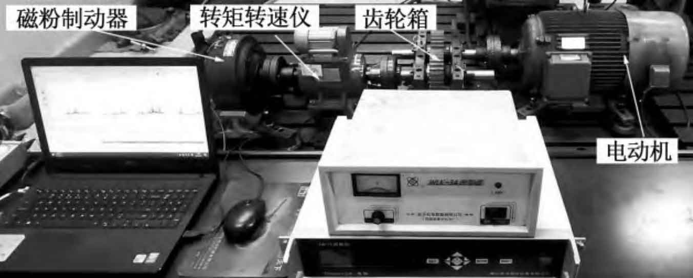
The spur gear vibration test bench consists of a drive motor, a transmission gearbox, a torque tachometer, and a magnetic particle brake. The on-site photos of the test bench are shown in Figure 2. Four acceleration sensors are installed at the radial and axial positions of the input and output shafts of the box, and the signals are collected and processed by the M+P tester. Figure 3 shows the specific locations of the four acceleration sensors.