As mentioned earlier, no matter how the number of teeth changes, the transition curve always exists and follows the formula. Therefore, when the number of teeth of a spur gear changes, the magnitude relationship between the base circle radius rb, the tooth root circle radius rf, and the starting point radius rG of the involute spur gear tooth profile essentially affects the tooth profile portion of the involute spur gear, and thus affects the time-varying meshing stiffness calculation of the involute portion. In addition, in practice, there is a minimum number of teeth Nmin to ensure that no undercutting occurs during the meshing process of spur gears. The minimum number of teeth Nmin=17. The classification of gear tooth models with a straight tooth number greater than 17 will be discussed. As mentioned earlier, the radius of the circle corresponding to the starting point of the involute tooth profile is always greater than the radius of the base circle.
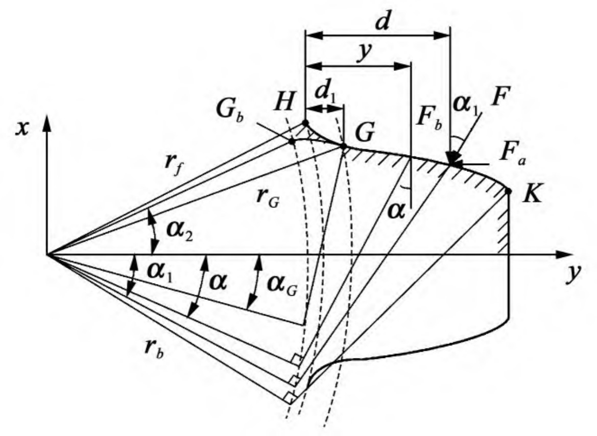
When the number of spur gear teeth meets 17<N ≤ 41, the gear tooth model is shown in Figure. According to elastic mechanics and material mechanics, the deformation energy of each part of the involute spur gear tooth profile KG is:
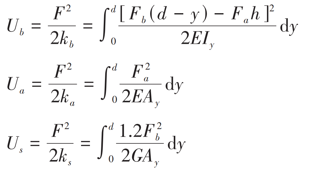
Where, y is the horizontal distance from any point on the involute to the base circle; d = rb cos α 1 + rb ( α 1 + α 2 )sin α 1 – rb cos α 2 is the horizontal distance from the action point P of the meshing force to the base circle; Iy and Ay are the moment of inertia and the cross-sectional area of the spur gear tooth section at a distance y from the base circle, respectively. The meaning of other parameters is as described above.
Combined with the geometric characteristics of the involute, the bending stiffness kb, the shear stiffness ks, and the axial compression stiffness ka can be expressed as the engagement angle, respectively α The function of, namely:
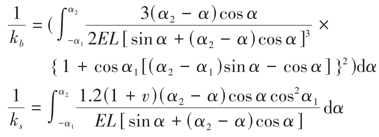
Where, α 2 = π/2N + inv α 0 is the half base tooth angle; The meaning of other parameters is as described above.
When the number of spur gear teeth meets N>41, the pressure angle at the starting point G of the actual involute spur gear tooth profile changes from α 2 becomes α G. Where, α 2 = π/2N + inv α 0 is the half base tooth angle; The meaning of other parameters is as described above.
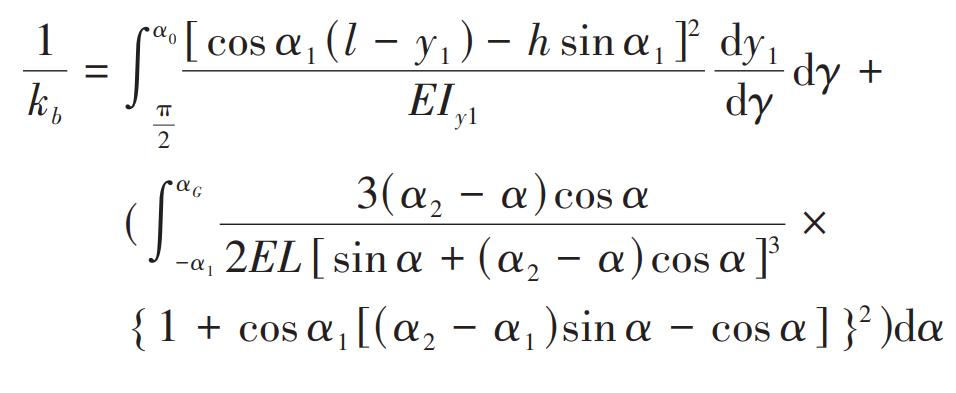
When the number of spur gear teeth meets N>41, the pressure angle at the starting point G of the actual involute spur gear tooth profile changes from α 2 becomes α G。 Taking bending stiffness as an example, combined with the geometric characteristics of involutes, the modified bending stiffness kb can be expressed as:
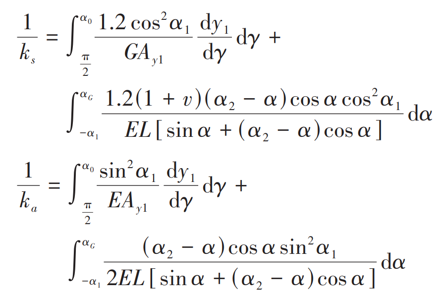
Similarly, the modified shear stiffness ks and axial compression stiffness ka expressions are:
In the formula, the meanings of other parameters are as described above.
In summary, when the number of spur gear teeth meets 17<N ≤ 41, combined with the formula, the bending, shear, and axial compression stiffness calculation formulas for the full tooth profile of spur gear teeth can be obtained as follows:
Similarly, when the number of teeth of a spur gear meets N>41, the stiffness calculation formulas for each part are: