
1. Finite Element Mesh Generation of Rotors
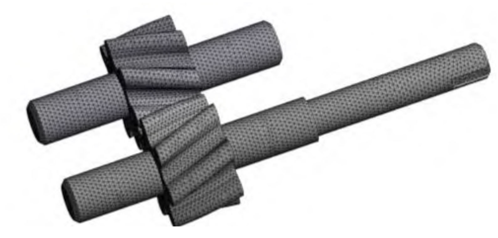
Utilize the Mesh function in Workbench for finite element mesh generation of structures, and choose the independent mesh generation method as Tetrahedrons, as shown in Figure 1. In addition, the coordinates of the watershed and the coordinates of the rotating pair are kept the same in their respective solvers, so that the fluid interface corresponds to the structural interface in contact.
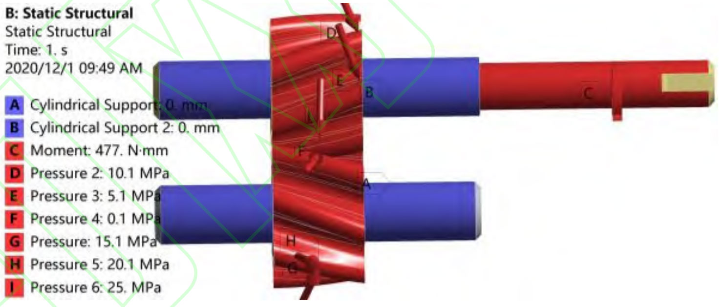
The fluid calculation region is subjected to steady-state calculations in Fluent, and the solid structure domain is subjected to static dynamic analysis in ANSYS Workbench. Apply cylindrical support at the contact point between the shaft and the sliding bearing to constrain its radial displacement, allowing for axial and tangential freedom. As shown in Figure 2, the boundary conditions of the rotating pair are set with inlet and outlet pressures, and the minimum pressure set at the inlet is 0. 1MPa, the maximum pressure set at the oil outlet is 25MPa, and the pressure value in the transition zone is evenly distributed from the low-pressure zone to the high-pressure zone.
2. Modal solution results with prestress
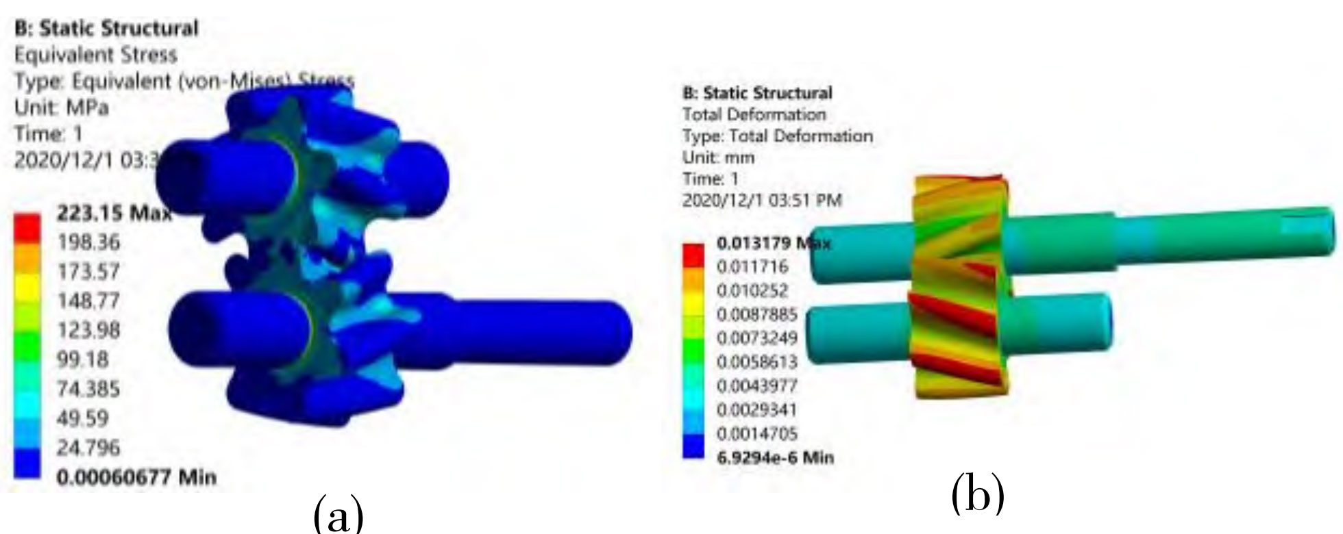
The deformation and stress analysis of the rotor under distributed load is shown in Figure 3, which will be used as a pre-stressed boundary condition to analyze the subsequent modes. From Figure 3, it can be seen that the deformation of the rotor gradually increases from the center outwards, with the maximum deformation occurring near the rotor flange and the minimum deformation on the shaft, with a maximum deformation of 0.013179mm. Due to the maximum force exerted by the rotor on the driven wheel, the maximum deformation of the driven wheel is greater than that of the driving wheel. The minimum equivalent stress of the rotor occurs on the shaft and near the wheel flange area, while the maximum equivalent stress occurs at the meshing position of the rotor tooth surface. The maximum equivalent stress is 223.15MPa, which is less than the yield strength and fatigue limit of the rotor material. Therefore, the rotor of the double arc helical gear pump will not undergo plastic deformation and fatigue damage.
The simulation results are used as pre-stress to analyze the modal of the rotating pair, and Figure 4 shows the modal data results of the double arc helical gear pump rotor.
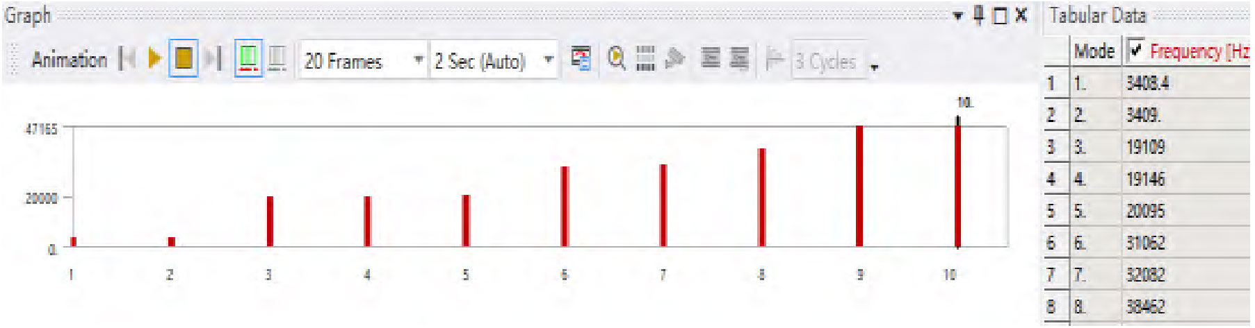
As shown in Figure 4, the first order frequency of the rotor of the double arc helical gear pump is 3408.4Hz, while the passing frequency of the double arc helical gear pump is 166.67Hz. Due to the fact that the passing frequency of the double arc helical gear pump is much lower than the natural vibration frequency of the rotor, resonance will not occur.