
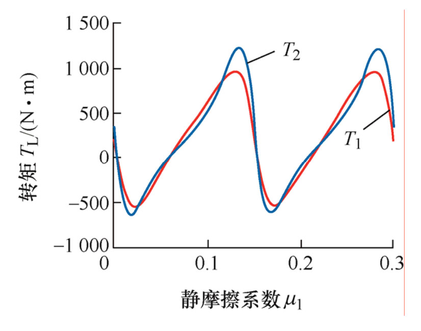
According to the formula, the torque allocated to the two drive wheels can be calculated, as shown in Figure 1, where T1 represents the torque of the differential to the left slipping drive wheel and T2 represents the torque of the differential to the right non slipping drive wheel. From Figure 1, it can be seen that the torque distributed on the two drive wheels is not constant, but periodic changes with alternating positive and negative values over time (where positive values represent the torque driving the car forward and negative values represent the torque driving the car backward). The reason for the phenomenon is that under the action of a non circular gear differential, the left sliding wheel will rotate in a non uniform motion pattern in one direction, and the wheel itself generates inertia torque. The combination of the resistance torque of the sliding wheel on the ground and the inertia torque of the wheel produces the variation pattern of T1 in Figure 1. The torque T2 allocated to the non slip side wheels has increased compared to T1, mainly due to the effect of internal friction torque in the differential. From the above analysis, it can be seen that the inertia torque of a slipping wheel has a significant impact on the torque distributed to the two drive wheels by non circular gears. As the amplitude of inertia torque rapidly increases with the increase of wheel speed, the peak values of T1 and T2 increase as the planetary carrier speed increases, thereby increasing the maximum traction of the entire vehicle. Therefore, in Experiment 1, the maximum traction generated by the differential will significantly increase with the planetary carrier speed, This is the theoretical mechanism of dynamic anti slip for variable transmission ratio differentials.
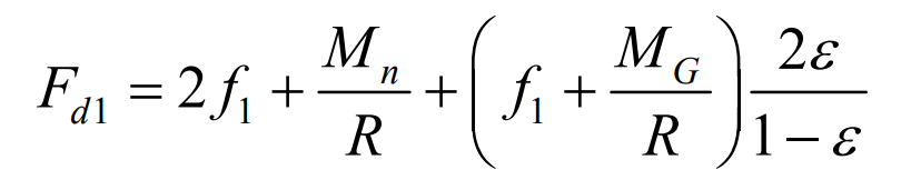
In the existing torque distribution of variable transmission ratio differentials, the inertia torque caused by the variable speed rotation of the slipping wheel is not considered, and only the torque on the two wheels is statically distributed according to the transmission ratio of the differential. Therefore, it is called a static anti slip mechanism. Based on this mechanism, the maximum static traction force formula can be obtained as:
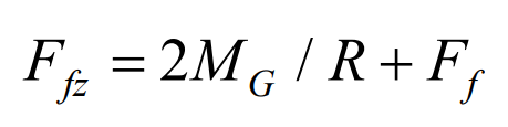
The expression for vehicle driving resistance can be derived from the formula:
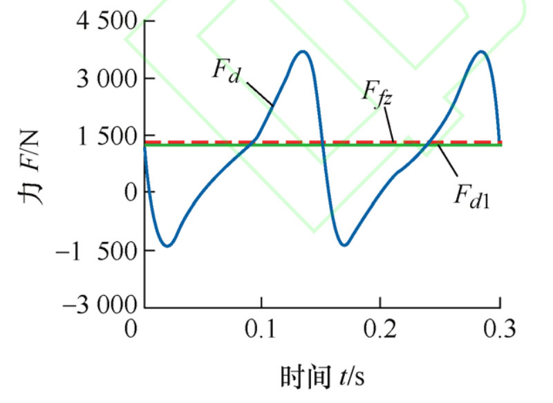
By using the formula, the time-varying dynamic traction force, maximum static traction force, and driving resistance of the vehicle can be calculated separately, as shown in Figure 2. According to the static anti slip mechanism, the Fd1 obtained is less than the driving resistance Ffz, and the vehicle will not be able to escape. However, according to the dynamic anti slip mechanism, the opposite conclusion is obtained. When the differential planetary carrier speed is 200 r/min, the time-varying dynamic traction force Fd will exceed Ffz in a local range. At this time, the dynamic traction force does positive work, and the vehicle will generate forward motion, Therefore, the dynamic anti slip mechanism can more accurately reflect the anti slip performance of the variable transmission ratio differential.