
Understanding the anatomy of bevel gears, including tooth geometry and angle calculations, is crucial for designing and analyzing these gear systems. Let’s explore the key elements of bevel gear anatomy:
- Pitch Diameter (D): The pitch diameter is the theoretical diameter of the gear at the point where the gear tooth profile intersects the reference cone. It is the main reference for gear sizing and calculations.
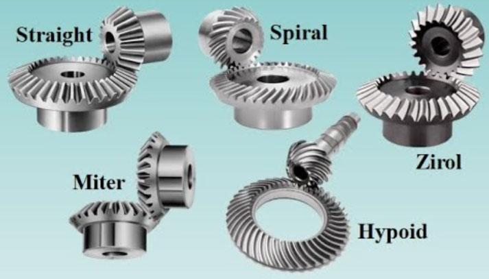
- Cone Angle (α): The cone angle is the angle between the axis of the gear and the generatrix of the gear cone. It determines the gear orientation and the type of bevel gear (straight, spiral, hypoid).
- Pitch Cone: The pitch cone is the imaginary cone that encompasses the gear’s pitch diameter and coincides with the gear tooth profile. For straight bevel gears, the pitch cone is identical to the reference cone. However, for spiral and hypoid bevel gears, the pitch cone deviates from the reference cone due to the helical tooth profile.
- Face Width (W): The face width is the axial length of the gear tooth along the gear’s width. It influences the gear’s load-carrying capacity and torque transmission capability.
- Number of Teeth (Z): The number of teeth represents the total count of gear teeth. It affects the gear ratio and influences the gear’s size and performance.
- Tooth Profile: The tooth profile refers to the shape of the gear tooth along its length. Different types of bevel gears, such as straight, spiral, or hypoid, have distinct tooth profiles. The tooth profile affects gear engagement, contact pattern, load distribution, and noise characteristics.
- Pitch Angle (β): The pitch angle is the angle between the tooth profile and a plane perpendicular to the gear axis. It is a critical parameter that determines the shape and contact characteristics of the gear teeth. The pitch angle is used in tooth geometry calculations and tooth contact analysis.
- Pressure Angle (θ): The pressure angle is the angle between the line tangent to the tooth profile at the pitch point and a line perpendicular to the gear’s pitch surface. It influences tooth contact, load distribution, and strength. Common pressure angles for bevel gears are 20° and 14.5°.
- Back Cone Distance (BCD): The back cone distance is the radial distance from the pitch cone apex to the intersection of the gear’s back cone surface with the gear’s axis. It affects the gear’s size, tooth engagement, and tooth contact pattern.
- Dedendum (h): The dedendum is the radial distance from the pitch circle to the bottom of the gear tooth. It ensures proper clearance between the gear teeth and facilitates smooth tooth engagement.
- Addendum (ha): The addendum is the radial distance from the pitch circle to the top of the gear tooth. It determines the height of the gear tooth and affects the gear’s strength and load-carrying capacity.
To calculate the tooth geometry and angles of bevel gears, various mathematical formulas and specialized software are available. These calculations consider parameters such as gear ratio, module, cone angles, pressure angles, and tooth dimensions to determine the precise tooth profile, contact pattern, and performance characteristics of the gear system.
It is important to note that bevel gear design and analysis can be complex, and consulting gear design references, standards, or specialized software tools is recommended to ensure accurate calculations and optimal gear performance.