Based on the analysis of the cutting principle of the tooth surface of the spherical involute involute involute spiral bevel gear, it can be seen that the cutter required by the new method of three-axis linkage cutting is different from the existing spiral bevel gear cutting cutter, and the cutter edge must be able to form the circular arc generating line of the spiral bevel gear tooth surface in the process of cutting the teeth at high speed. Therefore, this chapter calculates the key geometric parameters and designs the structure of bevel gear milling cutter according to the new method.
In order to further simplify the control of the tooth cutting movement, this chapter transforms the linkage of three rotation movements into the linkage of two rotation movements and one linear movement, and designs the tooth cutting movement scheme combining with the new designed tooth cutting tool.
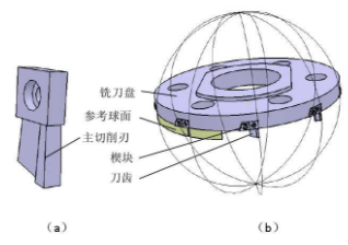
Because the generating line of the tooth surface of the spherical involute spiral bevel gear is arc-shaped, this paper uses the generating line as the cutting edge to cut the tooth surface. When the cutting edge rotates at high speed, it must be ensured that the cutting edge can form the arc-shaped cutting edge line. Through the comparison and comprehensive analysis of various blade shapes, it is finally determined to select the arc-shaped blade. When the cutting teeth rotate at high speed, the blade will form a hemispherical surface. Figure (a) is the CATIA three-dimensional model of the designed cutter tooth, and its main cutting edge is circular arc shape. In order to facilitate the clamping and dismantling of the cutter teeth and the correction and reuse of the worn blade, this paper selects the clamp type cutter, as shown in Fig. 3.1 (b). When the bevel gear is milled, the cutter rotates at a high speed, and the spatial trajectory of all the main cutting edges on the cutter head will form a part of the hemispherical surface.
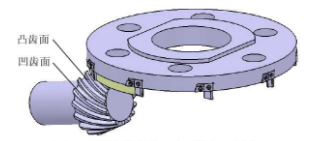
The main cutting edge of the milling tool is located on the outside of the cutter tooth. It is an external edge milling tool, which can only process the concave tooth surface of the spiral bevel gear. In order to describe the relative relationship between the external edge milling cutter and the spiral bevel gear to be machined in the processing of concave tooth surface vividly, the three-dimensional model of spiral bevel gear is established by CATIA software. , and in the assembly environment by adding constraints to establish the outside edge milling cutter machining spiral bevel gear concave tooth surface schematic diagram, as shown in the figure. If this cutter is used for milling the convex tooth surface, it will obviously over cut the solid part of the bevel gear teeth. Therefore, in order to process the convex tooth surface of the spiral bevel gear, an internal edge milling cutter must be designed.
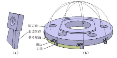
In order to describe the milling cutter with inner edge, which is needed to process the convex tooth surface of spiral bevel gear, CATIA software is used to build the three-dimensional model of milling cutter, as shown in the figure. When the cutter rotates at high speed in the process of cutting teeth, the spatial motion path of all the main cutting edges on the cutter head will form a part of the spherical surface, and all the main cutting edges are located inside the cutter teeth.
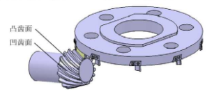
By using this kind of internal edge milling cutter, the convex tooth surface of spiral bevel gear can be milled, and the intersecting line between a part of hemispherical surface and (q) plane, which is the locus of spatial motion when the main cutting edge rotates at a high speed, is taken as the tooth surface generating line. According to the cutting principle of spherical involute tooth surface, it can be known that the convex tooth surface of spiral bevel gear can be machined only by three-axis linkage, and the processing diagram is as shown in the figure Show.