
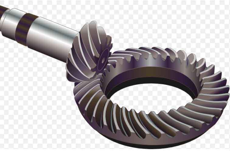
Spiral bevel gears are an essential component in various mechanical systems, ranging from automotive differentials to power tools. They are designed to transmit rotational motion and torque between intersecting shafts at a specific angle. Understanding the science behind spiral bevel gears involves examining their manufacturing process and tooth geometry. Let’s explore these aspects in more detail.
Manufacturing Process:
- Gear Cutting: The manufacturing of spiral bevel gears typically begins with gear cutting. The gear blank, usually a disc-shaped piece of metal, is precisely machined to the required size and shape.
- Tooth Generation: The gear’s teeth are generated using specialized cutting tools, such as gear-generating machines or CNC milling machines. These tools precisely remove material from the gear blank to form the gear teeth.
- Tooth Grinding: After tooth generation, the gear teeth undergo a grinding process to achieve a high degree of accuracy and surface finish. This step is crucial to ensure proper meshing and minimize noise and vibration during gear operation.
- Heat Treatment: Heat treatment is often applied to enhance the gear’s mechanical properties. Through processes like carburizing, the gear’s surface is hardened to improve its wear resistance, while the core remains relatively tough to handle the transmitted loads.
- Finishing Operations: After heat treatment, additional finishing operations such as deburring, polishing, and coating may be performed to further refine the gear’s surface quality and optimize its performance.
Tooth Geometry:
- Pitch Diameter: The pitch diameter is an imaginary circle that represents the average diameter of the gear, where the gear’s teeth effectively engage with each other. It is crucial for maintaining the desired gear ratio.
- Cone Angle: Spiral bevel gears have teeth that are cut on a cone. The cone angle is the angle between the gear’s axis and the generatrix of the gear cone.
- Pressure Angle: The pressure angle is the angle between the line tangent to the tooth profile at the pitch diameter and the gear’s axis. It affects the manner in which the gear teeth transmit force and influences the load-carrying capacity and efficiency.
- Tooth Profile: The tooth profile of a spiral bevel gear is usually defined by a mathematical curve such as an involute or cycloidal curve. These profiles ensure smooth engagement and minimize stress concentrations during gear meshing.
- Spiral Angle: Spiral bevel gears have spiral-shaped teeth that wrap around the gear cone. The spiral angle refers to the angle between a tooth’s generatrix and the gear’s axis. It enables gradual tooth engagement, resulting in smoother operation, reduced noise, and improved load distribution.
The science behind spiral bevel gears encompasses the precise manufacturing processes and the careful design of tooth geometry to achieve reliable and efficient power transmission. Engineers and manufacturers use advanced computational methods, such as computer-aided design (CAD) and finite element analysis (FEA), to optimize gear performance, strength, and durability.