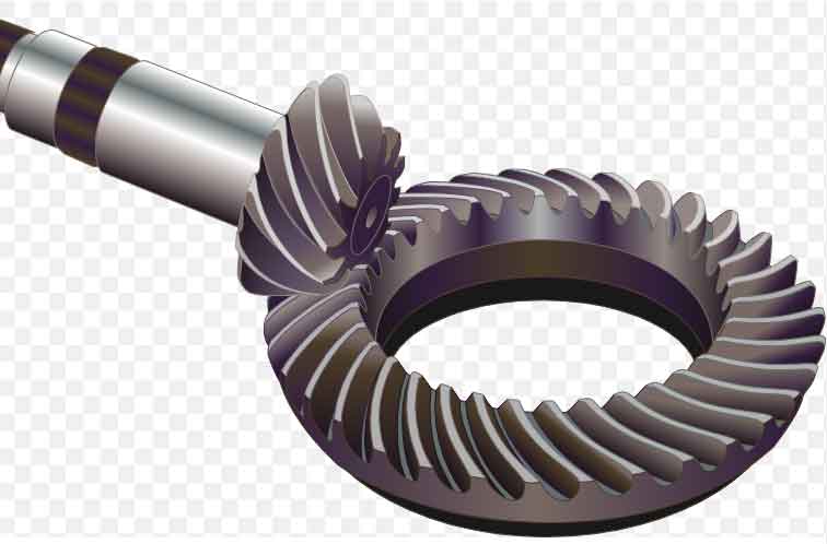
Designing and manufacturing spiral bevel gears involves translating theoretical principles into practical applications. Let’s explore the process of bringing theory into practice in gear design and manufacturing:

Requirements and Specifications:
The gear design process begins by understanding the specific requirements and specifications of the application. This includes factors such as torque, speed, operating conditions, space limitations, and noise considerations. Clear specifications provide the foundation for gear design and ensure that the resulting gears meet the desired performance criteria.
Gear Geometry Calculation:
Theoretical calculations are performed to determine the gear geometry based on the design requirements. Parameters such as pitch diameter, cone angle, pressure angle, tooth profile, and spiral angle are calculated using mathematical formulas and equations. These calculations help establish the initial design parameters for the gear.
Computer-Aided Design (CAD):
Once the initial design parameters are established, CAD software is used to create a detailed 3D model of the gear. CAD allows engineers to refine the gear geometry, incorporate design modifications, and visualize the gear assembly in a virtual environment. It facilitates the optimization of tooth profiles, clearance considerations, and overall gear performance.
Finite Element Analysis (FEA):
FEA is employed to analyze the structural integrity and performance of the gear under different load conditions. It helps identify potential stress concentrations, areas of high wear, and areas prone to failure. FEA enables engineers to optimize the gear design, improve its strength, and predict its performance under real-world operating conditions.
Manufacturing Process Selection:
The chosen manufacturing process depends on factors such as gear size, complexity, volume, material, and cost considerations. Common manufacturing methods for spiral bevel gears include gear cutting, CNC machining, and heat treatment processes. The selection of the appropriate manufacturing process ensures the efficient and accurate production of gears that meet the design specifications.
Prototyping and Testing:
Before mass production, prototype gears are manufactured to validate the design and evaluate their performance. Prototyping allows for physical testing, such as gear meshing analysis, noise and vibration measurements, and durability assessments. Testing provides feedback on the gear’s actual performance, allowing for design refinements and improvements.
Quality Control and Inspection:
Quality control measures are implemented throughout the manufacturing process to ensure the gears meet the required specifications. This includes dimensional inspections, surface finish assessments, and hardness testing. Advanced inspection techniques such as coordinate measuring machines (CMM) and gear checking machines are used to verify the gear’s dimensional accuracy and tooth geometry.
Continuous Improvement:
Gear design and manufacturing are iterative processes that involve continuous improvement. Feedback from field performance, customer requirements, and advancements in technology are incorporated into future design iterations. This iterative approach allows for the refinement and optimization of spiral bevel gears over time.
By combining theoretical knowledge with practical considerations, engineers and manufacturers can effectively design and produce spiral bevel gears that meet the required performance, reliability, and efficiency criteria. The integration of computer-aided design, advanced analysis tools, and quality control measures enables the realization of high-quality gears that excel in various applications.
