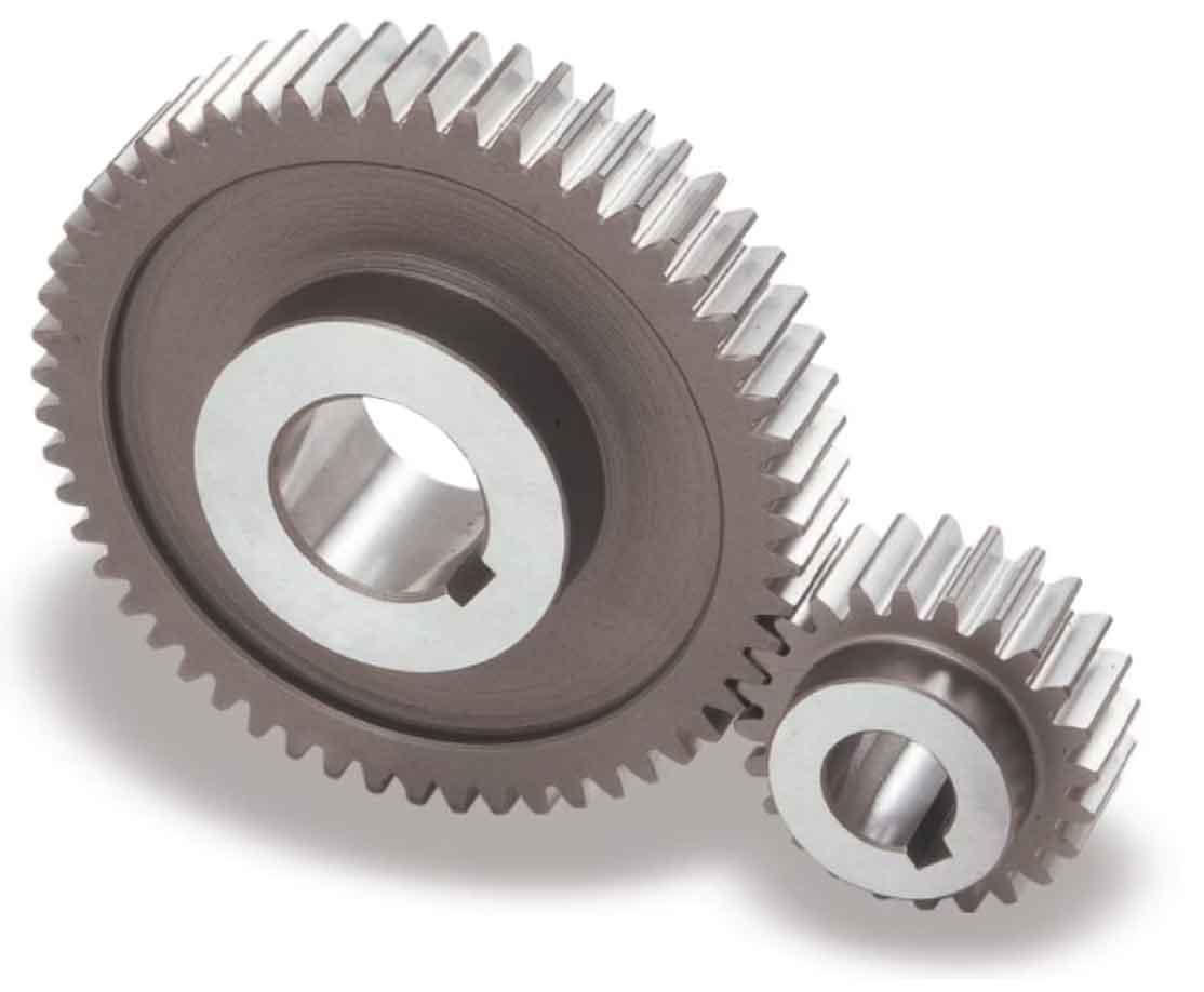
Designing spur gears involves considering various geometric parameters and performing calculations to ensure proper functionality and performance. Let’s explore the key aspects of spur gear geometry and the calculations involved in gear design:
1. Pitch Circle Diameter (PCD):
The pitch circle diameter is the theoretical circle that passes through the center of the gear and represents the effective size of the gear. It determines the tooth size and spacing. The PCD is calculated using the formula:
PCD = (Module or Diametral Pitch) x Number of Teeth
2. Module and Diametral Pitch:
The module and diametral pitch are parameters used to define the size and tooth dimensions of a spur gear. The module is the ratio of the PCD to the number of teeth, while the diametral pitch is the number of teeth per unit of diameter. They are related by the formula:
Module = 25.4 / Diametral Pitch
3. Addendum and Dedendum:
The addendum is the distance from the pitch circle to the top of the gear tooth, while the dedendum is the distance from the pitch circle to the bottom of the tooth space. They are calculated as a fraction of the module:
Addendum = Module Dedendum = 1.25 x Module
4. Tooth Thickness and Tooth Space:
The tooth thickness is the width of the gear tooth at the pitch circle, while the tooth space is the width of the gap between adjacent teeth. They are calculated as a fraction of the module:
Tooth Thickness = 0.5 x Module Tooth Space = Module – Tooth Thickness
5. Pressure Angle:
The pressure angle is the angle between the line tangent to the gear tooth profile at the pitch point and a line perpendicular to the gear’s axis. Commonly used pressure angles for spur gears are 20 degrees and 14.5 degrees. The pressure angle affects the force distribution and load-sharing characteristics of the gear teeth.
6. Helix Angle (For Helical Gears):
If designing helical gears, an additional parameter to consider is the helix angle, which represents the angle between the gear axis and the gear teeth. The helix angle affects the smoothness of tooth engagement and the load distribution along the tooth profile.
These are some of the key geometric parameters and calculations involved in spur gear design. It’s important to note that gear design requires careful consideration of the specific application requirements, including torque, speed, load distribution, and material properties. Design software or specialized gear design tools can assist in performing accurate calculations and generating gear geometry based on the desired specifications and standards.
