
Chapter 1: The Structure and Working Principle of Spiral Bevel Gear
Spiral bevel gear are a type of gears used in mechanical systems to transmit rotational motion and power between non-parallel shafts. They are designed to operate at right angles to each other and have tooth profiles that are cut spirally around the gear axis. This design allows for smoother engagement and quieter operation compared to straight bevel gear. Let’s break down the structure, components, and working principle of spiral bevel gear, as well as the influence of key parameters on their transmission performance.
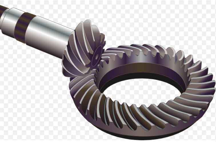
Structure and Components: Spiral bevel gear consist of two main components: the pinion gear and the main gear. These gears have conically shaped teeth that mesh with each other. The pinion gear is the smaller of the two and is typically mounted on a driving shaft, while the main gear is the larger one and is mounted on a driven shaft. The axes of these gears intersect at a right angle, allowing them to transmit motion and power efficiently between shafts that are not parallel.
Working Principle: When the driving shaft rotates, the pinion gear’s teeth come into contact with the teeth of the main gear. The spiral angle of the teeth allows for gradual engagement, resulting in smooth and gradual transmission of power. The spiral tooth profile ensures that multiple teeth are in contact at any given time, distributing the load across the gear teeth and reducing wear. The rolling action between the meshing teeth generates less friction and noise compared to straight bevel gear.
Influence of Parameters on Transmission Performance: Several parameters influence the transmission performance of spiral bevel gear:
- Main Gear and Pinion Gear Ratio: The gear ratio determines the speed and torque relationship between the input (pinion) and output (main gear) shafts. It affects the mechanical advantage and overall performance of the gear system.
- Helix Angle: The helix angle refers to the angle between the tooth trace and the gear axis. It affects the smoothness of engagement and disengagement between gear teeth. A smaller helix angle can result in higher axial thrust but smoother meshing.
- Number of Teeth: The number of teeth on both the pinion and main gear affects the gear ratio, contact pattern, and load distribution. Optimal tooth numbers should be chosen to ensure uniform load sharing and minimize stress concentration.
- Module (Pitch Diameter): The module is a measure of the gear size and affects the tooth dimensions. Proper module selection is crucial for ensuring the desired strength, durability, and load-bearing capacity of the gears.
- Gear Tooth Profile: The tooth profile influences the smoothness of meshing and the distribution of contact forces. An accurate and well-designed tooth profile is essential for efficient power transmission.
- Material and Heat Treatment: The choice of material and heat treatment process directly impacts the gears’ strength, wear resistance, and fatigue life.
- Alignment and Mounting: Precise alignment of the gears during assembly is critical for smooth operation and to avoid premature wear or failure.
- Lubrication: Proper lubrication is necessary to reduce friction, dissipate heat, and prevent wear between gear teeth.
By mastering these parameters and their influence on the transmission performance of spiral bevel gear, engineers can design and optimize gear systems for various applications, such as automotive, aerospace, industrial machinery, and more. Careful consideration of these factors ensures efficient and reliable power transmission while minimizing noise, vibration, and wear.
Chapter 2: Material Characteristics used in Manufacturing of Spiral Bevel Gear
Spiral bevel gear can be manufactured from a variety of materials, each with its own set of advantages and disadvantages. The choice of material depends on the specific application requirements, such as load capacity, wear resistance, corrosion resistance, operating conditions, and cost considerations. Here are some common materials used in the manufacturing of spiral bevel gear, along with their pros and cons:
1. Steel:
- Advantages: Steel is a commonly used material for spiral bevel gear due to its high strength, good wear resistance, and ability to handle heavy loads. It can be heat-treated to further enhance its mechanical properties.
- Disadvantages: Steel gears can be susceptible to corrosion if not properly protected. They may also generate more noise and require proper lubrication to minimize friction and wear.
2. Alloy Steel:
- Advantages: Alloy steels offer improved strength, hardness, and wear resistance compared to plain carbon steel. They are suitable for high-load applications and can be heat-treated for enhanced performance.
- Disadvantages: Alloy steels may still require protection against corrosion, and their cost can be higher compared to plain carbon steel.
3. Cast Iron:
- Advantages: Cast iron gears have good wear resistance and can handle moderate loads. They are also cost-effective to manufacture.
- Disadvantages: Cast iron gears are relatively brittle and may not be suitable for high-impact or shock-loading applications. They can be heavy and may require additional machining for precision.
4. Bronze and Brass Alloys:
- Advantages: Bronze and brass alloys offer good corrosion resistance and are often used in applications where lubrication may be limited. They are also self-lubricating to some extent.
- Disadvantages: These materials may have lower strength compared to steel and may not be suitable for high-load or high-impact applications. They are often used in lower-power and low-speed systems.
5. Powder Metallurgy (PM) Alloys:
- Advantages: PM alloys are designed to have controlled porosity, allowing for improved lubrication and quieter operation. They can offer a good balance of strength, wear resistance, and cost-effectiveness.
- Disadvantages: PM gears may have limitations in terms of load capacity compared to solid steel gears. The manufacturing process can also impact their consistency.
6. Plastics and Polymers:
- Advantages: Plastics and polymers can offer excellent corrosion resistance, lightweight design, and low noise operation. They are often used in applications requiring minimal lubrication.
- Disadvantages: Plastic gears may have limited load capacity and may not be suitable for high-temperature applications. They can also exhibit higher wear rates compared to metal gears.
7. Exotic Materials (Titanium, Stainless Steel, etc.):
- Advantages: Exotic materials can offer exceptional strength, corrosion resistance, and lightweight properties, making them suitable for demanding applications.
- Disadvantages: Exotic materials are often expensive and may require specialized manufacturing processes. Their use is typically reserved for high-performance or specialized applications.
In summary, the choice of material for manufacturing spiral bevel gear depends on the specific requirements of the application. Engineers must carefully consider factors such as load capacity, wear resistance, corrosion resistance, operating conditions, and budget constraints to select the most appropriate material that will ensure reliable and efficient gear performance over the gear’s lifespan.
Chapter 3: Design Method and Calculation Principle of Spiral Bevel Gear
Designing spiral bevel gear involves several key steps, including geometric parameter calculation, strength verification, and selection of transmission ratios. Here’s an overview of the design methods and calculation principles for spiral bevel gear:
1. Geometric Parameter Calculation:
- Pitch Cone Angle: Determine the required angle between the gear axes (shaft angles). This angle is crucial for proper meshing and efficient power transmission.
- Helix Angle: Choose an appropriate helix angle that balances smooth engagement, load distribution, and axial thrust. Helix angle affects gear performance and axial forces.
- Number of Teeth: Calculate the number of teeth for both the pinion and the main gear. It should satisfy the desired gear ratio and ensure proper tooth engagement.
- Module (Pitch Diameter): Determine the module based on torque, speed, and load requirements. The module affects gear size, strength, and tooth dimensions.
2. Strength Verification:
- Lewis Formula: Use the Lewis formula to calculate the allowable bending stress and determine if the gears meet strength requirements. The formula considers factors like load, material properties, tooth geometry, and quality.
- AGMA Standards: Refer to American Gear Manufacturers Association (AGMA) standards for gear design and rating. AGMA provides guidelines and formulas for gear geometry, load distribution, and tooth stress analysis.
- Finite Element Analysis (FEA): Conduct FEA simulations to analyze stress distribution, deflection, and deformation under various loads and conditions. FEA helps validate gear strength and performance.
3. Tooth Profile and Contact Pattern:
- Gleason Method: The Gleason method is commonly used for generating spiral bevel gear’ tooth profiles. It involves cutter design, gear generation, and adjustment to achieve desired contact patterns and tooth engagement.
- Contact Pattern Analysis: Ensure proper contact and load distribution by analyzing tooth contact patterns. Adjust gear parameters to achieve optimal contact pattern for smooth operation and even wear.
4. Lubrication and Efficiency:
- Lubrication Analysis: Calculate lubrication parameters such as film thickness, pressure distribution, and friction losses. Proper lubrication ensures reduced wear, heat generation, and efficient power transmission.
- Efficiency Calculation: Estimate gear efficiency by considering friction losses, meshing characteristics, and lubrication effects. Aim for high efficiency to minimize power loss.
5. Selection of Transmission Ratios:
- Gear Ratio Selection: Choose gear ratios that match the desired speed and torque requirements of the system. Consider factors like input speed, output speed, and mechanical advantage.
- Interference and Clearance: Ensure sufficient backlash (clearance) between gear teeth to prevent interference during operation. Backlash affects smooth engagement and noise levels.
6. Manufacturing Considerations:
- Manufacturability: Design gears with manufacturability in mind, considering factors like cutter availability, machining capabilities, and tolerances.
- Heat Treatment: Account for the effects of heat treatment on material properties, distortion, and residual stresses during gear design.
It’s important to note that gear design is a complex process that requires expertise, software tools, and thorough analysis. Modern CAD software often includes modules for gear design and analysis, which can help streamline the design process and ensure accurate calculations. Additionally, consulting relevant standards and guidelines, such as AGMA standards, is crucial for designing safe and reliable spiral bevel gear.
Chapter 4: The Performance Simulation of Spiral Bevel Gear
Computer simulation and simulation techniques play a vital role in studying the performance of spiral bevel gear, allowing engineers to analyze stress distribution, deformation, and other factors to optimize design and predict gear system performance. Here’s how computer simulation is used in this context:
Finite Element Analysis (FEA): Finite Element Analysis is a powerful simulation technique used to model and analyze the behavior of complex structures, including spiral bevel gear. FEA involves discretizing the gear geometry into small elements, each represented by mathematical equations. These equations are solved to predict how the gear will respond to different loads and conditions.
Applications of FEA for Spiral Bevel Gear:
- Stress Analysis: FEA predicts stress distribution within the gear teeth, tooth roots, and other critical areas. Engineers can identify high-stress regions and adjust gear geometry or material properties to improve strength and durability.
- Deformation Analysis: FEA helps predict gear deformation under different loads, enabling the evaluation of gear tooth deflection, misalignment effects, and overall gear geometry changes.
- Contact Analysis: Simulation can predict the contact pattern between gear teeth during meshing, allowing engineers to optimize tooth profiles and alignment for even load distribution.
- Heat Generation and Distribution: FEA can model heat generation and distribution within the gear system, helping to analyze temperature rise and thermal effects on gear performance.
- Dynamic Analysis: Simulations can analyze dynamic behavior, including vibration, resonance, and dynamic loading, helping to optimize gear design for reduced noise and vibration.
Benefits of FEA for Spiral Bevel Gear:
- Virtual Prototyping: FEA allows engineers to test and iterate designs in a virtual environment before physical production, reducing the need for costly prototypes and trial-and-error testing.
- Optimization: Simulation enables optimization of gear geometry, material selection, and other parameters to achieve desired performance goals.
- Predictive Analysis: FEA provides insights into how gears will perform under different conditions, aiding in predicting gear system behavior and potential failure modes.
- Performance Evaluation: Engineers can evaluate the impact of design changes on gear performance quickly and efficiently.
- Cost and Time Savings: FEA reduces the need for physical testing, leading to significant cost and time savings during the design and development process.
Software Tools: Several commercial software packages are available for performing FEA on spiral bevel gear. These tools allow engineers to input gear geometry, material properties, loading conditions, and other parameters to simulate gear behavior accurately.
In summary, computer simulation and FEA techniques provide a powerful means to study and optimize the performance of spiral bevel gear. By analyzing stress distribution, deformation, contact patterns, and other factors, engineers can refine gear designs, improve durability, reduce noise and vibration, and ensure optimal performance in various applications.
Chapter 5: The Manufacturing Process of Spiral Bevel Gear
The manufacturing process of spiral bevel gear involves several steps, including processing, heat treatment, surface treatment, and more. Each of these steps has a significant impact on gear quality and performance. Let’s explore the manufacturing process in detail and understand its influence on gear characteristics:
1. Gear Processing:
- Blank Preparation: Start with raw material, usually steel or alloy steel, in the form of bars, sheets, or forgings. Cut or shape the blanks to approximate gear dimensions.
- Machining: Use various machining processes like turning, milling, and grinding to achieve precise gear tooth profiles, dimensions, and finishes. CNC (Computer Numerical Control) machines are often used for accurate machining.
- Tooth Forming: Generate the tooth profiles using methods like gear hobbing, gear shaping, or gear grinding. Gear hobbing is a common method for spiral bevel gear, producing accurate tooth profiles and desired helix angles.
2. Heat Treatment:
- Carburizing: Apply carburizing heat treatment to enhance the surface hardness and wear resistance of gear teeth. This process involves introducing carbon into the gear surface, followed by quenching and tempering.
- Through-Hardening: Alternatively, gears can undergo through-hardening to achieve uniform hardness throughout the gear. This process involves quenching and tempering the entire gear to improve its overall strength.
3. Surface Treatment:
- Shot Peening: Perform shot peening to improve the fatigue resistance of gear surfaces. Shot peening induces compressive stresses that counteract tensile stresses, enhancing gear durability.
- Surface Coatings: Apply coatings like nitriding or DLC (Diamond-Like Carbon) to further enhance surface hardness, wear resistance, and corrosion resistance.
4. Gear Assembly and Inspection:
- Assembly: Assemble the pinion and main gear with precise alignment and backlash control. Proper assembly ensures smooth and efficient power transmission.
- Quality Control: Conduct various inspections, including gear tooth profile measurement, gear runout testing, contact pattern analysis, and dimensional checks, to ensure gear accuracy and performance.
5. Gear Finishing:
- Deburring and Finishing: Remove burrs and sharp edges from the gear teeth to improve meshing and reduce stress concentrations. Finishing processes like honing or lapping can enhance tooth surface quality.
Impact on Gear Quality and Performance:
- Dimensional Accuracy: Accurate machining and heat treatment ensure correct gear dimensions, leading to proper meshing and load distribution.
- Tooth Profile and Contact Pattern: Precise tooth profile generation and gear assembly influence the contact pattern, ensuring smooth and even load sharing across gear teeth.
- Surface Hardness and Wear Resistance: Heat treatment and surface treatments improve hardness and wear resistance, prolonging gear lifespan and reducing wear-related failures.
- Fatigue Resistance: Shot peening, surface coatings, and proper heat treatment improve fatigue resistance, enhancing gear durability under cyclic loads.
- Backlash Control: Proper assembly and machining help control backlash, affecting gear engagement and noise levels.
- Material Selection: The choice of material affects gear strength, toughness, and response to heat treatment.
- Alignment: Precise gear assembly and alignment minimize misalignment-related issues and noise.
- Surface Finish: Proper finishing reduces friction, wear, and noise during gear operation.
The manufacturing process of spiral bevel gear plays a crucial role in determining gear quality, performance, and durability. Each step, from initial processing to final inspection, contributes to the overall characteristics of the gears, ensuring reliable and efficient power transmission in various applications.
Chapter 6: Lubrication and Cooling Methods in Spiral Bevel Gear Transmission
Lubrication and cooling are essential aspects of ensuring the stability, durability, and efficiency of spiral bevel gear transmissions. Proper lubrication reduces friction, wear, and heat generation, while effective cooling helps dissipate heat and maintain optimal operating conditions. Here’s an overview of lubrication and cooling methods for spiral bevel gear systems:
Lubrication Methods:
- Splash Lubrication: This method involves immersing the gears partially or fully in a lubricating oil reservoir. As the gears rotate, they pick up lubricant and distribute it across the tooth surfaces. Splash lubrication is simple and effective for many applications.
- Forced Lubrication: In forced lubrication, a pump actively circulates lubricating oil through channels, nozzles, or spray systems to ensure consistent and controlled oil distribution to gear contact areas. This method is particularly suitable for high-speed and heavy-duty applications.
- Oil Mist Lubrication: Oil mist is generated by mixing lubricating oil with air, creating a mist that is directed onto the gears. Oil mist lubrication provides a fine, continuous oil film on gear surfaces, enhancing lubrication efficiency.
- Oil Jet Lubrication: Oil jets direct a high-pressure stream of lubricant onto specific gear contact areas, ensuring targeted and intensive lubrication. This method is used in critical areas or for gear sets operating under extreme conditions.
Cooling Methods:
- Natural Convection: Allow heat to dissipate naturally from the gear housing through convection. Adequate ventilation and cooling fins on the housing promote airflow and heat dissipation.
- Forced Air Cooling: Use fans or blowers to actively circulate air over the gear housing. Forced air cooling is effective in removing excess heat and maintaining proper operating temperatures.
- Cooling Fluids: Circulate a cooling fluid (e.g., water or oil) through cooling jackets or passages in the gear housing. The fluid absorbs heat from the gears and carries it away, helping to regulate temperature.
- Heat Exchangers: Integrate heat exchangers into the gear system to transfer heat from the lubricating oil to an external cooling medium, such as water or air.
Combined Lubrication and Cooling:
- Oil Jet Lubrication with Cooling: High-pressure oil jets not only lubricate but also provide cooling by carrying away heat from the gear surfaces.
- Oil Mist Lubrication with Cooling: Oil mist lubrication can also serve as a cooling method, as the oil mist absorbs heat and is carried away by the air circulation.
Impact on Gear System:
- Proper lubrication reduces friction, wear, and heat generation, thereby extending gear life and minimizing the risk of failures.
- Effective cooling prevents overheating, which can lead to premature wear, material degradation, and loss of efficiency.
- Lubrication and cooling methods help maintain consistent gear performance and reduce the likelihood of downtime or maintenance issues.
- Adequate lubrication and cooling contribute to smooth operation, reduced noise, and optimized power transmission efficiency.
- The choice of lubrication and cooling methods should be based on factors such as gear design, operating conditions, load, speed, and temperature requirements.
Overall, a well-designed lubrication and cooling strategy is crucial for ensuring the stability, durability, and efficiency of spiral bevel gear transmissions, especially in demanding or high-performance applications.
Chapter 7: Vibration and Noise in Spiral Bevel Gear Transmission

Vibration and noise issues can arise in spiral bevel gear transmission due to factors such as gear misalignment, manufacturing variations, dynamic loading, and resonance. These issues can impact gear performance, durability, and overall system efficiency. Here’s an overview of possible vibration and noise problems in spiral bevel gear and how to reduce or avoid them through design and control methods:
1. Gear Misalignment:
- Issue: Misalignment of spiral bevel gear can lead to uneven load distribution, increased tooth contact stresses, and vibration.
- Mitigation: Ensure precise alignment during gear assembly. Proper alignment reduces unnecessary forces and wear on gear teeth.
2. Manufacturing Variations:
- Issue: Inconsistent manufacturing processes can result in variations in gear dimensions and tooth profiles, leading to uneven contact and increased noise.
- Mitigation: Implement quality control measures and tight manufacturing tolerances. Use advanced manufacturing techniques to ensure uniformity.
3. Dynamic Loading and Resonance:
- Issue: Dynamic loads or resonant frequencies in the gear system can amplify vibration and noise.
- Mitigation: Adjust gear geometry, material properties, and design parameters to minimize resonant frequencies. Use dynamic analysis and simulation to predict and address potential resonance issues.
4. Tooth Contact Patterns:
- Issue: Improper tooth contact patterns can lead to concentrated stresses, resulting in noise and wear.
- Mitigation: Optimize tooth profiles and alignment to achieve uniform contact patterns. Use contact pattern analysis and simulation to verify proper tooth engagement.
5. Lubrication and Surface Finish:
- Issue: Inadequate lubrication or poor surface finish can result in friction, heat, and wear, leading to noise and vibration.
- Mitigation: Ensure proper lubrication and surface treatment. Use high-quality lubricants and improve surface finish to reduce friction and wear.
6. Gear Meshing Quality:
- Issue: Poor gear meshing quality can lead to impact and backlash-related noise and vibration.
- Mitigation: Optimize gear tooth profiles, manufacturing processes, and assembly techniques to achieve precise meshing and minimize backlash.
7. Structural Resonance:
- Issue: Structural resonances within the gear housing or surrounding components can amplify noise and vibration.
- Mitigation: Design gear housings and support structures to minimize resonance effects. Use vibration analysis and finite element simulations to identify potential resonance points.
8. Damping and Isolation:
- Issue: Inadequate damping and isolation between gear components can allow vibration to propagate and amplify.
- Mitigation: Integrate damping materials or mechanisms into the gear system to absorb and dissipate vibration energy. Isolate gear components from surrounding structures to prevent vibration transfer.
9. Tooth Modifications:
- Issue: Certain tooth modifications, such as crowning or tip relief, can be used to reduce noise and improve load distribution.
- Mitigation: Apply appropriate tooth modifications based on the specific application and operating conditions.
10. Regular Maintenance:
- Mitigation: Implement a proactive maintenance program that includes gear inspection, lubrication, and adjustments to address wear and potential vibration issues before they escalate.
Addressing vibration and noise issues in spiral bevel gear transmission involves a combination of careful design, precise manufacturing, proper assembly, and advanced analysis techniques. By considering these factors and implementing appropriate measures, engineers can optimize gear performance, reduce noise, and enhance the durability and efficiency of spiral bevel gear systems.
Chapter 8: Performance and characteristics of spiral bevel gear
Spiral bevel gear are just one type of gear configuration among several others, each with its own set of advantages and disadvantages. Let’s compare spiral bevel gear to some other common types of gears, considering factors like transmission efficiency, noise, load-bearing capacity, and more:
1. Spiral Bevel Gear vs. Straight Bevel Gear:
- Advantages of Spiral Bevel Gear:
- Smoother and quieter operation due to gradual tooth engagement.
- Better load distribution across multiple teeth, reducing wear.
- Higher load-bearing capacity and torque transmission.
- Reduced axial thrust compared to straight bevel gear.
- Disadvantages of Spiral Bevel Gear:
- More complex manufacturing and setup process.
- Slightly lower transmission efficiency compared to straight bevel gear.
2. Spiral Bevel Gear vs. Helical Gear:
- Advantages of Spiral Bevel Gear:
- Can handle higher axial loads and are more suitable for right-angle drives.
- Less sliding action between teeth, resulting in higher efficiency.
- More compact design for right-angle drives compared to helical gear.
- Disadvantages of Spiral Bevel Gear:
- More challenging to manufacture and set up than helical gears.
- Typically generate more noise compared to helical gears.
3. Spiral Bevel Gear vs. Worm Gear:
- Advantages of Spiral Bevel Gear:
- Higher efficiency due to rolling contact between teeth.
- Lower heat generation and friction losses compared to worm gear.
- Suitable for higher-speed applications compared to worm gear.
- Disadvantages of Spiral Bevel Gear:
- Limited gear ratios and efficiency in some cases.
- More complex design and manufacturing process.
4. Spiral Bevel Gear vs. Planetary Gear:
- Advantages of Spiral Bevel Gear:
- Simpler design and assembly compared to complex planetary gear systems.
- More suitable for high torque and heavy-duty applications.
- Lower manufacturing complexity compared to planetary gear.
- Disadvantages of Spiral Bevel Gear:
- May not achieve the same gear reduction ratios as planetary gear systems.
- Larger physical size compared to compact planetary gear systems.
5. Spiral Bevel Gear vs. Hypoid Gear:
- Advantages of Spiral Bevel Gear:
- Generally smoother and quieter operation compared to hypoid gears.
- More suitable for applications requiring high torque and heavy loads.
- Disadvantages of Spiral Bevel Gear:
- Hypoid gears can achieve higher gear ratios and more compact designs.
- Hypoid gears can provide more flexibility in gear positioning.
Spiral bevel gear offer advantages such as smoother operation, higher load-bearing capacity, and better torque transmission compared to some other gear types. However, they can be more complex to manufacture and set up. The choice of gear type depends on the specific application requirements, including speed, torque, noise, efficiency, space constraints, and manufacturing considerations. Each gear type has its own trade-offs, and selecting the most suitable type requires a careful analysis of these factors.
Chapter 9: The Reliability Analysis of Spiral Bevel Gear System
Reliability analysis of spiral bevel gear systems involves assessing the system’s lifespan, failure probability, and overall performance to ensure safe and reliable equipment operation. Reliability analysis helps engineers identify potential failure modes, optimize design, and implement maintenance strategies. Here’s an overview of how reliability analysis is conducted for spiral bevel gear systems:
1. Failure Modes and Effects Analysis (FMEA):
- Identify potential failure modes, such as tooth breakage, wear, pitting, misalignment, etc.
- Assess the effects of each failure mode on system performance, safety, and functionality.
- Assign severity, occurrence, and detection ratings to each failure mode to prioritize them for mitigation.
2. Reliability Prediction:
- Estimate the expected lifespan and reliability of the gear system using statistical models and historical data.
- Consider factors such as load, speed, material properties, lubrication, and operating conditions.
- Use tools like reliability block diagrams to analyze the overall reliability of the gear system and its components.
3. Failure Probability Analysis:
- Calculate the probability of failure for different failure modes using probability distributions and reliability analysis methods.
- Consider factors such as loading variations, material variability, and manufacturing uncertainties.
4. Weibull Analysis:
- Apply Weibull distribution to model failure rates over time.
- Analyze failure data to determine the shape and scale parameters of the distribution.
- Predict the gear system’s cumulative failure probability and reliability over its operational life.
5. Monte Carlo Simulation:
- Conduct simulations that model different variables and uncertainties affecting gear performance.
- Generate multiple scenarios to assess the range of possible outcomes and failure probabilities.
6. Maintenance Strategies:
- Develop preventive and predictive maintenance plans based on reliability analysis results.
- Schedule inspections, lubrication, and component replacements to minimize the risk of failure and ensure safe operation.
7. Design Improvements:
- Based on reliability analysis findings, optimize gear design to mitigate high-risk failure modes.
- Modify gear geometry, material selection, or manufacturing processes to improve system reliability.
8. Sensitivity Analysis:
- Analyze how changes in parameters, such as load, lubrication, or material properties, affect gear system reliability.
- Identify critical factors that significantly influence system performance and prioritize them for control.
9. Reliability Growth Analysis:
- Continuously monitor gear system performance over time and update reliability predictions as new data becomes available.
- Implement corrective actions and design changes based on observed failures to improve reliability.
10. Statistical Process Control (SPC):
- Monitor key process parameters during manufacturing to control variability and improve gear quality.
- Implement SPC techniques to ensure consistent and reliable gear production.
Reliability analysis helps engineers make informed decisions regarding design, maintenance, and operational strategies to ensure the safe and efficient operation of spiral bevel gear systems. By understanding failure modes, estimating failure probabilities, and implementing appropriate measures, engineers can enhance gear system reliability, minimize downtime, and optimize the lifespan of equipment.
Chapter 10: The Maintenance of Spiral Bevel Gear
Maintenance of spiral bevel gear involves a combination of preventive, predictive, and corrective measures to ensure their optimal performance and extend their lifespan. Fault diagnosis technology plays a crucial role in assessing the working and health status of gear systems. Here’s an overview of maintenance methods for spiral bevel gear and how fault diagnosis technology is used:
Maintenance Methods for Spiral Bevel Gear:
- Preventive Maintenance:
- Regular Inspection: Conduct routine visual inspections to check for wear, damage, misalignment, and lubrication issues.
- Lubrication: Ensure proper and timely lubrication of gear components to reduce friction and wear.
- Alignment: Verify gear alignment to prevent uneven loading and tooth contact issues.
- Tightening and Fastening: Regularly check and tighten fasteners, bolts, and connections.
- Predictive Maintenance:
- Vibration Analysis: Monitor vibration levels to detect abnormal patterns or trends indicative of gear issues.
- Thermography: Use infrared cameras to identify overheating or hotspots in the gear system.
- Oil Analysis: Analyze lubricating oil to detect contamination, wear particles, and changes in lubricant properties.
- Acoustic Emission Testing: Detect stress waves produced by gear defects to identify early signs of damage.
- Corrective Maintenance:
- Gear Replacement: Replace worn or damaged gears with new or reconditioned ones.
- Tooth Repairs: Repair minor damage or wear on gear teeth through grinding or other methods.
- Misalignment Correction: Adjust gear alignment to improve meshing and contact patterns.
- Resurfacing: Address minor surface imperfections through resurfacing or honing.
Fault Diagnosis Technology for Spiral Bevel Gear:
- Vibration Analysis:
- Monitor vibration signatures to identify frequency patterns associated with gear defects, such as pitting, misalignment, or wear.
- Use spectrum analysis to identify specific frequencies related to gear meshing and diagnose problems.
- Acoustic Emission (AE) Testing:
- AE sensors detect stress waves generated by gear defects, allowing early detection of issues like crack propagation or tooth breakage.
- AE signals are analyzed to determine the severity and type of defect.
- Thermography:
- Infrared cameras capture heat distribution on gear surfaces, revealing hotspots associated with friction, misalignment, or insufficient lubrication.
- Temperature anomalies can help identify potential problem areas.
- Oil Analysis:
- Analyze lubricating oil samples for wear particles, contaminants, viscosity changes, and chemical degradation.
- Changes in oil properties provide insights into gear wear and potential issues.
- Non-Destructive Testing (NDT):
- Techniques such as magnetic particle testing or dye penetrant testing can identify surface cracks and defects in gear components.
- Finite Element Analysis (FEA):
- Simulate gear behavior using FEA to predict stress distribution, deformation, and contact patterns under different operating conditions.
- Machine Learning and AI:
- Implement machine learning algorithms to analyze data trends and patterns, aiding in early fault detection and predictive maintenance.
By utilizing these maintenance methods and fault diagnosis technologies, operators can assess the working condition and health status of spiral bevel gear, enabling timely interventions, reducing downtime, and ensuring reliable gear system performance.