
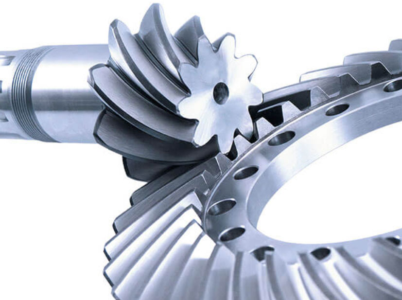
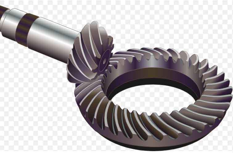
Spiral bevel gears combine the characteristics of both spiral gears and bevel gears. They consist of a helical gear and a bevel gear, and the teeth of the helical gear and the bevel gear mesh with each other to achieve power transmission. This unique design allows spiral bevel gears to transmit motion between intersecting shafts while also providing the benefits of helical gears, such as smoother engagement and reduced noise compared to straight bevel gears.
The spiral tooth shape on the helical gear allows for gradual tooth engagement, leading to smoother and quieter operation compared to straight-cut teeth. The helix angle of the teeth introduces a sliding motion during engagement, which helps distribute the load and reduce impact forces.
Spiral bevel gears are commonly used in various applications that require efficient power transmission at angles, including automotive differentials, aerospace systems, industrial machinery, and more. Their design allows for efficient torque transfer, higher load-carrying capacity, and improved durability, making them suitable for demanding and high-performance applications.
Chapter 1: The Helical Angle of Spiral Bevel Gears
The helix angle is a fundamental characteristic of spiral bevel gears, and it plays a significant role in achieving smooth force and motion transmission while minimizing meshing impact. The helix angle causes the gear teeth to be inclined or slanted relative to the gear axis, rather than being perpendicular as in straight bevel gears. This slanted tooth orientation has several important benefits:
- Smooth Engagement and Contact: The helix angle allows for gradual and continuous engagement of the gear teeth. As the gear rotates, the inclined teeth mesh progressively, resulting in a smoother and quieter transition between teeth compared to straight-cut gears. This gradual engagement reduces impact forces and minimizes noise during gear operation.
- Load Distribution: The sliding motion created by the helix angle helps distribute the load more evenly across the teeth. This distributes the forces over a larger contact area, reducing localized stress and wear. The load-sharing characteristic enhances the gear’s load-carrying capacity and overall durability.
- Reduced Axial Thrust: The helix angle generates axial thrust forces that tend to offset each other, helping to counteract any tendency of the gears to move along the axis. This feature is particularly important in applications where axial movement needs to be minimized.
- Contact Ratio: The helix angle increases the contact ratio, which is the number of teeth in contact at any given moment. A higher contact ratio results in smoother load transmission and improved distribution of forces.
- Noise Reduction: The gradual meshing and reduced impact forces contribute to quieter gear operation, making spiral bevel gears suitable for applications where noise is a concern.
The combination of the helix angle’s features makes spiral bevel gears well-suited for applications requiring both efficient power transmission and smooth, reliable operation. They are widely used in industries such as automotive, aerospace, industrial machinery, and more, where their ability to transmit forces and motion with reduced impact and noise is a significant advantage.
Chapter 2: The Transmission Performance of Spiral Bevel Gears
The transmission performance of spiral bevel gears is critical for ensuring optimal functionality in specific applications. Several key factors contribute to the overall performance of spiral bevel gears:
1. Transmission Ratio:
- The transmission ratio determines the speed relationship between the input and output shafts. It’s crucial to match the gear ratio with the application requirements to achieve the desired speed reduction or increase.
- The gear ratio is determined by the number of teeth on the gear and pinion. Proper selection ensures that the gear system meets the intended speed and torque requirements.
2. Transmission Efficiency:
- Transmission efficiency measures the effectiveness of power transfer between gears. It is affected by factors such as gear tooth geometry, surface quality, lubrication, and loading conditions.
- Efficient transmission minimizes power losses due to friction, heat, and other factors, contributing to overall system energy efficiency.
3. Torque Transmission Ability:
- The torque transmission capability of spiral bevel gears is crucial in applications with high loads or torque requirements.
- The gear design, material selection, and manufacturing processes must be optimized to handle the maximum torque without failure or excessive wear.
4. Load Distribution and Tooth Contact:
- Proper tooth contact and load distribution are essential to prevent concentrated stresses on gear teeth. The helix angle of spiral bevel gears contributes to even load distribution.
- Achieving a well-centered and properly aligned tooth contact pattern ensures uniform stress distribution and extends gear life.
5. Noise and Vibration:
- Helical gears in spiral bevel gears systems help reduce noise and vibration due to their gradual tooth engagement. Proper gear design and manufacturing processes can further minimize noise and vibration levels.
- Quiet operation is particularly important in applications where noise is a concern, such as automotive differentials.
6. Durability and Wear Resistance:
- The choice of materials, heat treatment, and surface treatments impact gear durability and wear resistance. Gears must withstand the operating conditions and potential abrasive forces they may encounter.
- Proper lubrication and maintenance contribute to prolonging gear life and maintaining performance.
7. Lubrication and Cooling:
- Effective lubrication ensures reduced friction, wear, and heat generation in the gear mesh. Adequate cooling mechanisms are necessary to manage heat dissipation in high-performance applications.
8. Tolerance and Accuracy:
- Tight tolerances and accurate manufacturing are crucial to ensure proper gear meshing, minimize backlash, and achieve the desired performance characteristics.
Optimizing these factors requires a comprehensive approach that includes proper gear design, material selection, manufacturing processes, quality control, and ongoing maintenance. By addressing these considerations, manufacturers can ensure that spiral bevel gears deliver reliable and efficient transmission performance in various applications.
Chapter 3: The Meshing Method of Spiral Bevel Gears
one of the key advantages of the meshing method of spiral bevel gears. The gradual contact and separation of each pair of teeth during the transmission process contribute to several benefits:
1. Smoother Engagement:
- The helical tooth profiles of spiral bevel gears enable gradual contact as the teeth come into mesh. This results in a smooth and progressive engagement between the gear teeth, reducing sudden impact and shock loading.
2. Reduced Noise and Vibration:
- The gradual meshing process and continuous tooth engagement help minimize noise and vibration. Unlike the abrupt engagement of straight-cut gears, the helical teeth of spiral bevel gears result in quieter operation by spreading the forces and vibrations over a larger contact area.
3. Improved Load Distribution:
- The gradual meshing action allows for better load distribution across the gear teeth. This helps distribute the applied force more evenly, reducing the risk of concentrated stresses on individual teeth.
4. Enhanced Transmission Efficiency:
- By minimizing impact forces and improving load distribution, spiral bevel gears can achieve higher transmission efficiency. Reduced friction and smoother engagement contribute to less energy loss during transmission.
5. Lower Wear and Extended Gear Life:
- The reduced impact and smoother engagement result in less wear on the gear teeth, potentially extending the lifespan of the gears and reducing the need for frequent maintenance or replacements.
6. High Torque Transmission:
- The gradual engagement of spiral bevel gears allows them to handle high torque transmission more effectively. The helical tooth profiles can distribute torque more evenly, preventing concentrated loads on specific teeth.
The meshing method of spiral bevel gears, characterized by the helical tooth profiles and gradual engagement, enhances the overall performance of the gears. This design feature is particularly advantageous in applications where noise reduction, smooth operation, and efficient power transmission are critical factors, such as automotive differentials, aerospace systems, and industrial machinery.
Chapter 4: The Advantages of Spiral Bevel Gears
The key advantages of spiral bevel gears transmission accurately. The unique characteristics of spiral bevel gears make them well-suited for specific applications that demand high precision, high load-carrying capacity, and long lifespan. Here’s a closer look at how these advantages translate into benefits for various industries:
1. High Transmission Efficiency:
- The gradual engagement of helical tooth profiles in spiral bevel gears contributes to high transmission efficiency. This efficiency is particularly valuable in applications where minimizing energy loss is essential, such as industrial machinery and automotive drivetrains.
2. Smooth Motion and Low Noise:
- The helical tooth design of spiral bevel gears results in smooth and quiet gear operation due to the gradual tooth engagement. This characteristic is crucial in applications where noise reduction and smooth motion are critical, such as precision machinery, robotics, and automotive differentials.
3. High Precision and Accuracy:
- Spiral bevel gears are capable of transmitting motion with high precision and accuracy. This precision is advantageous in applications requiring tight tolerances and accurate motion control, such as CNC machine tools, gearboxes, and aerospace systems.
4. High Load-Carrying Capacity:
- The design of spiral bevel gears allows for efficient load distribution across the tooth surfaces. This load-sharing capability makes them suitable for applications that involve heavy loads, such as construction equipment, mining machinery, and marine propulsion systems.
5. Long Lifespan and Durability:
- The smooth engagement and load distribution of spiral bevel gears contribute to reduced wear and longer gear lifespan. This durability is essential in applications where frequent maintenance or gear replacements are impractical or costly, such as wind turbine gearboxes and heavy-duty industrial equipment.
6. Versatility in Various Industries:
- Spiral bevel gears find applications in diverse industries, including automotive, aerospace, manufacturing, marine, and more. Their ability to combine high precision, load-carrying capacity, and durability makes them adaptable to a wide range of mechanical systems.
It’s important to note that while spiral bevel gears offer significant advantages, their design and manufacturing complexity can make them more challenging to produce and maintain compared to other gear types. However, advancements in manufacturing technologies, digital design tools, and quality control methods have contributed to making spiral bevel gears more accessible and feasible for various applications. As industries continue to demand high-performance and reliable gear solutions, the attributes of spiral bevel gears make them a valuable choice for meeting those requirements.
Chapter 5: The Application Fields of Spiral Bevel Gears
Some of the key industries and fields where spiral bevel gears find widespread application. Let’s delve a bit deeper into these sectors and how spiral bevel gears play a crucial role:
1. Industrial Machinery:
- Spiral bevel gears are commonly used in industrial machinery such as machine tools, printing presses, textile machinery, and packaging equipment.
- Their ability to transmit high-power and high-torque movements makes them suitable for heavy-duty applications where precision, durability, and efficient power transmission are essential.
2. Transportation and Automotive:
- In the automotive industry, spiral bevel gears are integral components of differential assemblies, transferring power from the drive shaft to the wheels.
- They contribute to smooth motion, efficient torque distribution, and reduced noise in automotive drivetrains.
- Additionally, spiral bevel gears may be used in transmission systems, especially in high-performance and off-road vehicles.
3. Aerospace and Aviation:
- Spiral bevel gears are employed in aerospace applications, including helicopter and aircraft transmission systems.
- They help transfer power and torque in aerospace systems, where precision and reliability are critical for safe and efficient operation.
4. Military and Defense Equipment:
- Military vehicles, tanks, and armored vehicles often rely on spiral bevel gears to transmit power to differentials and wheels.
- These gears contribute to reliable and robust performance in challenging environments.
5. Power Equipment and Energy Generation:
- Spiral bevel gears can be found in power generation equipment such as wind turbines and hydroelectric generators.
- They play a role in transmitting rotational motion from the turbine to the generator, contributing to efficient energy conversion.
6. Marine and Shipbuilding:
- Spiral bevel gears are used in marine propulsion systems, where they help transmit power from engines to propellers.
- They are also employed in shipbuilding for various mechanical systems.
Spiral bevel gears’ ability to transmit high torque, accommodate varying load conditions, and provide smooth and efficient power transmission makes them versatile components across a wide range of industries. Their unique characteristics contribute to enhanced performance, durability, and reliability in applications that demand precision, high loads, and long lifespan. As technology and manufacturing processes continue to advance, spiral bevel gears are likely to play an even more significant role in shaping the machinery and systems of the future.
Chapter 6: The Manufacturing Process of Spiral Bevel Gears
The Manufacturing spiral bevel gears requires precise machining techniques to achieve the desired quality and accuracy. Different methods can be employed in the production of these gears, each offering its own advantages and considerations. Here are some common manufacturing methods used for spiral bevel gears:
1. Milling:
- Milling involves removing material from a workpiece using rotary cutters. Spiral bevel gears can be milled on specialized machines equipped with special cutters that create the desired tooth profiles.
- Milling offers flexibility in producing gears with different tooth geometries, helix angles, and ratios.
- It is suitable for producing small to medium batches of gears and can achieve good precision and surface finish.
2. Grinding:
- Gear grinding is a precision machining process that uses abrasive grinding wheels to remove material and achieve the desired tooth profile.
- Gear grinding ensures tight tolerances, excellent surface finish, and accurate gear geometry.
- It is well-suited for high-precision applications and is often used for finishing operations after other manufacturing methods.
3. Hobbing:
- Hobbing is a common method for producing spiral bevel gears. It involves using a specialized tool called a hob to create the gear teeth.
- The hob is gradually fed into the workpiece, and as the workpiece rotates, the teeth are generated through the cutting action of the hob.
- Hobbing is efficient for high-volume production and can achieve good accuracy and surface finish.
4. Form Cutting:
- Form cutting involves using a cutting tool with the negative profile of the gear teeth to create the desired tooth geometry.
- This method is suitable for producing spiral bevel gears with specific tooth profiles and is often used for small-scale or specialized production.
5. Lapping and Honing:
- After the initial machining process, lapping and honing can be employed to improve the gear tooth surface finish and ensure accurate tooth contact.
- Lapping involves rubbing the gear teeth against a lapping tool with abrasive paste to achieve a precise fit and better contact pattern.
- Honing is a similar process that uses a rotating abrasive tool to achieve a smooth tooth surface.
The choice of manufacturing method depends on factors such as the required precision, gear specifications, production volume, and available equipment. Regardless of the method used, tight process control, quality assurance measures, and skilled operators are essential to ensure the final product meets the required standards for quality, accuracy, and performance.
Chapter 7: The Stress Analysis of Spiral Bevel Gears
Stress analysis is a crucial step in the design and evaluation of spiral bevel gears to ensure their stability, reliability, and overall performance. Several factors must be considered during stress analysis:
1. Gear Geometry:
- The geometry of the gear teeth, including the helix angle, tooth profile, and pitch, influences how forces are distributed and transmitted through the gears.
- The meshing characteristics, such as contact ratio and backlash, impact how loads are shared and affect the stress distribution.
2. Load Conditions:
- The applied loads, including torque, bending, and axial forces, are critical factors affecting gear stress. The analysis must consider both static and dynamic loads.
- Variable loads and shock loads should be considered if the gear system experiences rapid changes in torque or abrupt start/stop conditions.
3. Material Properties:
- The material properties of the gear and pinion, including strength, modulus of elasticity, and fatigue resistance, significantly impact the gear’s ability to withstand loads without failure.
4. Lubrication and Friction:
- The effects of lubrication and friction should be accounted for in stress analysis to understand how they affect the distribution of forces and wear patterns on the gear teeth.
5. Tooth Contact Pattern:
- The analysis should consider the tooth contact pattern during meshing. An optimal contact pattern ensures even load distribution and minimizes concentrated stresses.
6. Misalignment and Deflection:
- Misalignment between gear axes or deflection under load can lead to uneven stress distribution and premature wear. Analyzing these factors helps optimize gear design.
7. Dynamic Effects:
- Dynamic effects such as resonance, natural frequencies, and vibration should be assessed to prevent potential gear failure due to excessive dynamic stresses.
8. Finite Element Analysis (FEA):
- FEA is a powerful tool used to simulate and analyze the stress distribution, deformation, and load-sharing behavior of spiral bevel gears under various conditions.
- FEA allows for detailed modeling of the gear system, considering complex geometries, material properties, and loading scenarios.
By conducting comprehensive stress analysis, designers can ensure that the spiral bevel gears are designed to withstand the expected loads and operating conditions while maintaining stability, reliability, and longevity. Advanced simulation techniques and computer-aided design tools play a significant role in accurately predicting gear performance and identifying potential stress concentration areas, enabling designers to make informed decisions and optimize gear designs.
Chapter 8: The Spiral Bevel Gears Transmission Generates Vibration and Noise
Managing vibration and noise in spiral bevel gears transmission is crucial to ensure a positive user experience, protect equipment, and maintain efficient operation. Here are some strategies and considerations to reduce vibration and noise in spiral bevel gears systems:
1. Gear Design Optimization:
- Proper gear design can help reduce vibration and noise. Optimizing tooth profiles, helix angles, and gear ratios can minimize impact forces during meshing, leading to smoother and quieter operation.
2. Precision Manufacturing:
- Accurate manufacturing processes, tight tolerances, and high-quality machining can help ensure proper gear meshing and minimize irregularities that contribute to noise and vibration.
3. Lubrication and Friction Management:
- Proper lubrication is essential to reduce friction and wear, which can contribute to vibration and noise. Using high-quality lubricants and maintaining appropriate lubrication levels is crucial.
- Lubrication additives and surface coatings can also help reduce friction and dampen vibrations.
4. Damping and Isolation:
- Incorporating damping elements, such as elastomeric couplings or vibration dampers, can help absorb and dissipate vibrations before they propagate through the system.
- Mounting gears on resilient supports or using isolators can prevent vibration transmission to surrounding structures.
5. Gear Alignment and Maintenance:
- Proper gear alignment and regular maintenance are essential to prevent misalignment-induced vibration and noise. Ensuring precise gear meshing and inspecting for wear can mitigate these issues.
6. Noise Control Measures:
- Implementing noise control measures such as enclosures, shields, or sound-absorbing materials can help contain and reduce noise generated by gear operation.
7. Vibration Analysis and Monitoring:
- Regular vibration analysis and monitoring can help identify potential issues before they escalate. It allows for timely maintenance and adjustments to prevent excessive vibration and noise.
8. Material Selection:
- Choosing materials with good damping properties can help absorb vibrations and reduce noise. Selecting materials with favorable acoustic characteristics can contribute to noise reduction.
9. Resonance Avoidance:
- Identifying and avoiding resonant frequencies in the gear system through design modifications or vibration damping can prevent excessive vibrations and noise amplification.
10. Computational Analysis:
- Using computational tools like Finite Element Analysis (FEA) and Computational Fluid Dynamics (CFD) can simulate gear behavior and aid in identifying potential noise and vibration sources.
By implementing these strategies and conducting thorough analysis, designers and engineers can significantly reduce vibration and noise levels in spiral bevel gears transmission systems. This not only improves the user experience and equipment longevity but also contributes to safer and more efficient operation.