
The rapid development of Chinese industry requires spur gears to have long service life, fatigue resistance, and high reliability, that is, spur gears are required to have higher surface integrity. Among numerous finishing techniques, rolling finishing not only reduces the surface roughness of the workpiece, refines the surface texture of the workpiece, and improves the residual stress on the workpiece surface, but also has the characteristics of easy processing of complex shaped parts and low cost. Therefore, it is widely used in the finishing of parts.
Spindle type rolling and finishing is a common finishing process for spur gears, which can improve the surface integrity of spur gears, remove burrs, chamfer, reduce noise, improve transmission efficiency, and obtain isotropic tooth surfaces.
Research has shown that the surface contact force and particle impact velocity of the workpiece have a significant impact on the material removal, residual stress, and roughness of the workpiece during spindle rolling and finishing. Many scholars at home and abroad have studied the contact force and impact velocity of particles. ITOH et al. verified through experiments that the product of particle contact force and particle impact velocity is directly proportional to the material removal rate on the workpiece surface. Wang Na et al. used dynamic force sensors to test the effects of particle size, workpiece installation position, and contact force on the surface processing effect of the workpiece. They found that the best processing effect was achieved when the particle diameter was small and the workpiece burial depth was small.
HASHIMOTO et al. used strain gauges to measure the contact force of workpieces in spindle rolling finishing, and proved that there is a strong correlation between the height of particle accumulation above the workpiece and the contact force. The higher the accumulation height, the greater the contact force. MALKORRA et al. demonstrated through experiments that the higher the stacking height above the workpiece in spindle rolling finishing, the greater the normal and tangential stress on its surface. They also found that conical particles can cause greater stress on the workpiece surface. Some scholars have also used high-speed cameras to measure and analyze the velocity of particles in spindle type rolling and polishing.
CARIAPA et al. calculated the approximate tangential velocity of particles at the interface of the particle swarm through measurement. TAN et al. developed a submersible particle tracker to measure and analyze the particle velocity inside the particle swarm.
Rolling and finishing work is a typical free grinding tool finishing technology. Compared with other finishing methods, its processing technology is mainly based on experience and requires multiple experiments and error testing. With the development of 3D printing, the finishing of non-standard and structurally complex parts has gradually become a trend, so the prediction of the optimal finishing process is particularly important. At present, most of the research on spindle type rolling and finishing machining directly measures the contact force and motion speed of particles. However, research on the interface between particles and workpieces is very limited, and the behavior of particles is difficult to clarify. Modeling and predicting changes in surface roughness of parts in rolling and finishing machining technology is still a major challenge.
Based on the Discrete Element Method (DEM), simulation and simulation of spindle type rolling and finishing machining are carried out to address the problems of direct observation. The motion and action mode of particles on the tooth surface of spur cylindrical gears are explored, and the influence of different machining parameters on the particle action on the tooth surface of spur cylindrical gears is analyzed by changing relevant machining parameters. Finally, experimental verification of the simulation results is carried out.
1. Principle of spindle type rolling and finishing machining
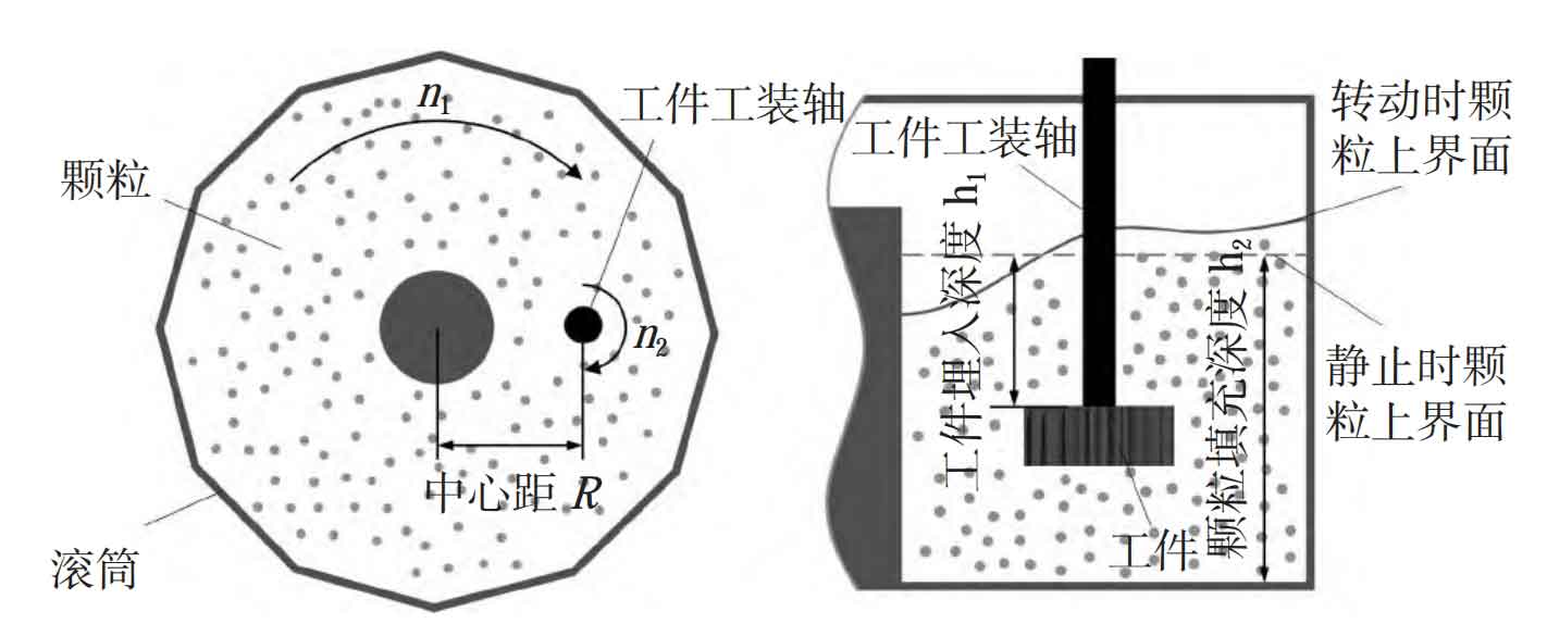
The principle of spindle type rolling and polishing is shown in Figure 1, mainly composed of a drum, particles, workpiece, and fixture. During processing, the fixture and drum rotate simultaneously, generating relative motion and interaction forces between particles and the workpiece, thereby achieving surface machining of the workpiece.
2. Discrete element simulation
To investigate the machining effect of particles on spur cylindrical gears in spindle rolling and finishing machining, EDEM software was used for discrete element simulation, and the contact model was based on the Hertz Mindlin slip free contact model of Archard wear theory.
2.1 Establishment of Discrete Element Model
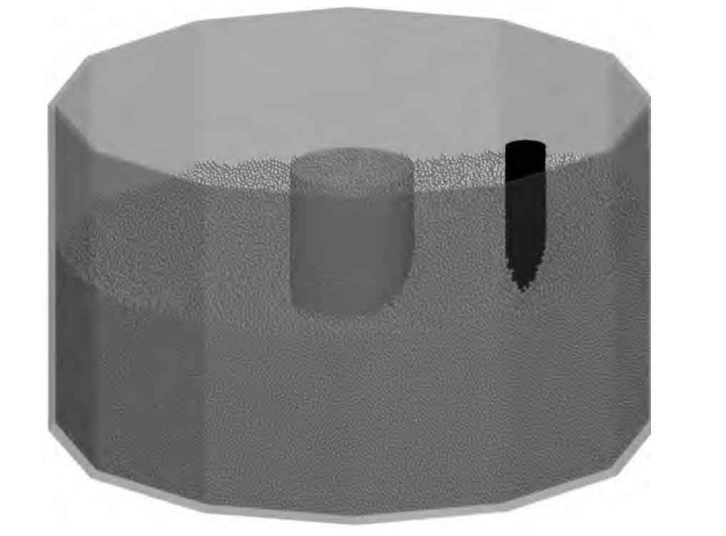
The discrete element model of the drum is shown in Figure 2. The particles are selected as spherical brown corundum with a diameter of 3 mm, and the gears are selected as spur gears with a modulus of m=5 mm, a tooth number of z=23, a tooth width of b=40 mm, and a pressure angle of 20 °. The intrinsic parameters and contact parameters of particles and drum materials are shown in Table 1 and Table 2, respectively. Set the Rayleigh time step to 20% and simulate 3 gear rotation cycles.
| Material parameters | Density ρ / (kg · m-3) | Poisson’s ratio ε | Shear modulus E/MPa |
| Drum (steel) | 7 850 | 0.300 | 7 940 |
| Particle (brown corundum) | 2 675 | 0.360 | 1 260 |
| Gear (40 Cr) | 7 870 | 0.277 | 8 080 |
| Interaction | Collision recovery coefficient μ1 | Static friction coefficient μ2 | Rolling friction coefficient μ3 |
| Granules-Drum | 0.50 | 0.35 | 0.10 |
| Particle-Gear | 0.43 | 0.36 | 0.10 |
| Particle-Particle | 0.46 | 0.39 | 0.10 |
2.2 Discrete Element Simulation Design
According to the Archard wear calculation model, the surface wear depth of spur gears is directly proportional to the pressure of particles on the spur gear and the relative motion speed of particles on the spur gear, that is:
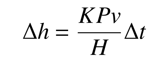
In the formula: depth of workpiece wear, m; Non dimensional wear coefficient; P is the unit normal pressure, Pa; V is the relative velocity of motion, m/s; H is the working hardness, Pa; ∆ Wear time t, s.
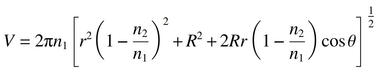
According to equation (1), the normal pressure of the unit and the relative velocity of particle motion are the key factors for material removal from the workpiece. Equation (2) is the formula for calculating the relative motion speed between particles and workpieces in the ideal spindle type rolling and finishing machining. It can be inferred from Equation (2) that the relative motion speed of particles can be changed by changing the speed of the spur gear and the drum, but the speed ratio of the drum to the spur gear needs to be kept constant. Due to the fixed speed ratio of the experimental equipment, the set speed ratio is the same as the equipment, with n1: n2=5:4. By changing the burial depth of the workpiece, the unit normal pressure on the surface of spur gears can be changed. Therefore, a single factor experiment was designed to simulate the speed and burial depth of spur gears and drums, exploring the effects of these two factors on contact force and impact speed. Table 3 lists the parameters for simulation. During simulation, the distance between the upper end face of the spur gear and the particle surface when the drum is stationary is set to be (i.e. the depth of embedding of the spur gear workpiece), and the distance between the bottom of the drum and the particle surface when the drum is stationary is set to be h2 (i.e. the depth of particle filling).
| Gear embedding depth h1/mm | Drum speed n1/(r · min ^ − 1) |
| 80,110,140 | 12,21,30 |
In the formula: V is the relative motion speed between the spur gear and the particles, m/s; N1 is the drum speed, r/min; N2 is the rotational speed of the spur gear, r/min; Center distance between R drum and spur gear, mm; R is the distance from the moving point on the tooth surface to the axis of the spur cylindrical gear, mm; The angle between the line connecting the axis of the moving point and the spur gear, and the line connecting the two centers of the spur gear and the drum, rad.
3. Simulation results and analysis
3.1 Particle flow field analysis
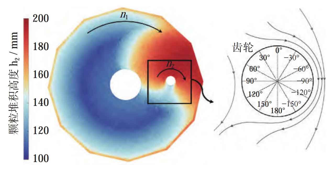
For spindle type rolling and finishing without workpieces, the rotational motion of the drum causes the upper interface of the particle group in the cylinder to appear as a parabolic surface. When the workpiece is inserted, the flow of particles is blocked by the workpiece, and the original flow form is broken. The particles accumulate at the front end of the workpiece, causing a difference in the stacking height between the front and rear ends of the workpiece, thereby affecting the contact force between the particles and the workpiece. Figure 3 shows the cloud map of the stacking height at the upper interface of the particle swarm under the working condition of h1=80 mm and n1=30 r/min. From Figure 3, it can be seen that the moving particles are obstructed by the spur gear and fixture shaft, resulting in a higher particle accumulation in the front end of the spur gear -150 ° to 120 ° than in the stationary state (the accumulation height in the stationary state is 140.00 mm), with a maximum accumulation height of 192.23 mm. Among them, there is a significant decrease in the particle stacking height in the -150 ° -90 ° and 90 ° -120 ° regions, while a cavity area below the static stacking height is generated in the 120 ° -150 ° region at the rear end of the spur gear, that is, on the motion wake of the spur gear. The maximum height difference between the front and rear ends of the spur gear reaches 70.00 mm. Figure 4 shows the velocity cloud map of particle movement. Due to the collision between the particle group and the workpiece, the kinetic energy of the particles at the front end of the spur gear decreases and the direction changes. Part of the kinetic energy is converted into the potential energy for particle climbing, while the other part is converted into internal energy used for friction between the particles themselves and the spur gear. At the rear end of the spur gear (90 ° to -90 ° area in Figure 3), the potential energy of the particles is converted into kinetic energy, causing them to accelerate and slide down. As shown in Figure 5, select three planes (a, b, and c) of the spur gear with a thickness of 6 mm (which are the center planes of the spur gear in three directions) to observe the flow of particles near the spur gear.
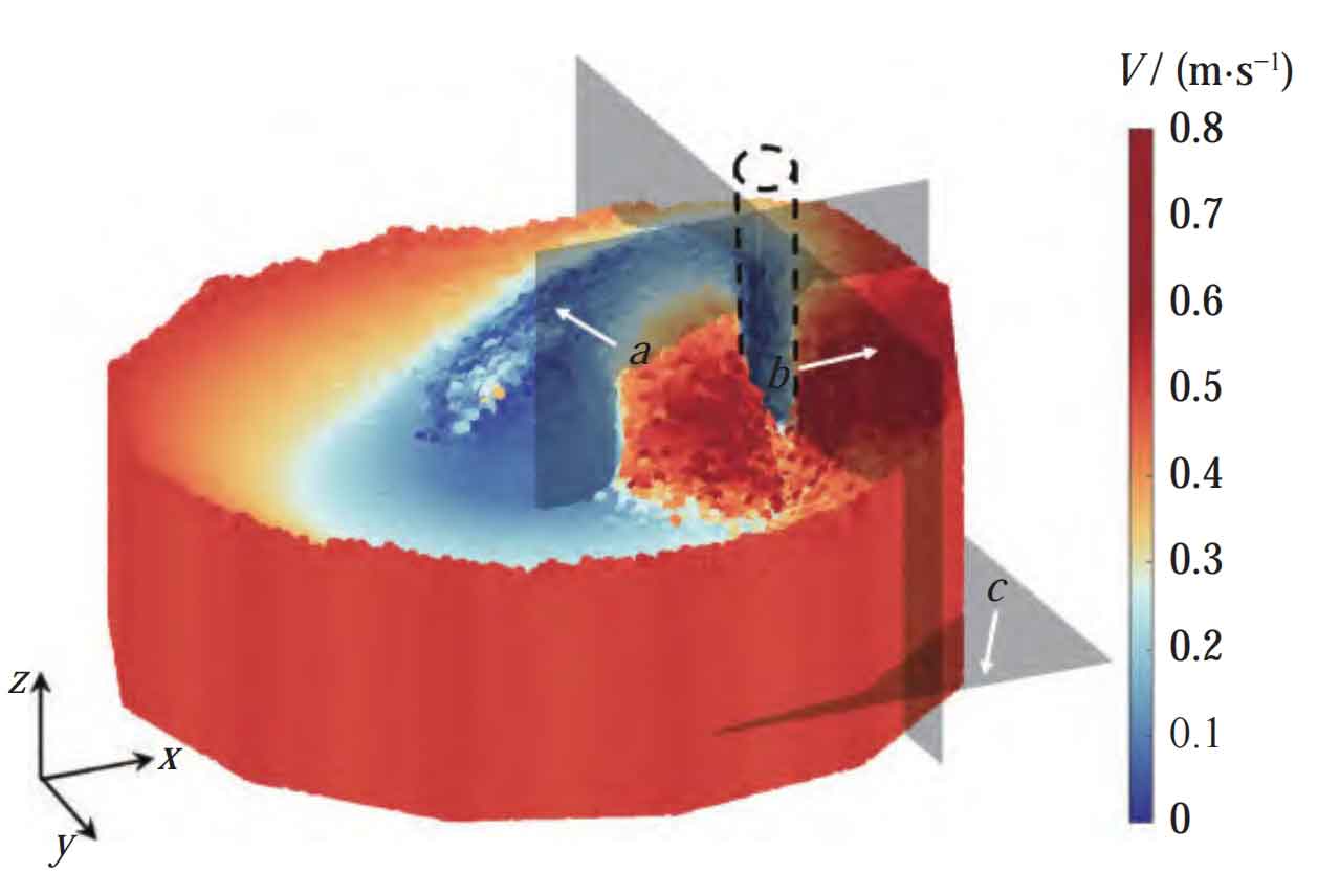
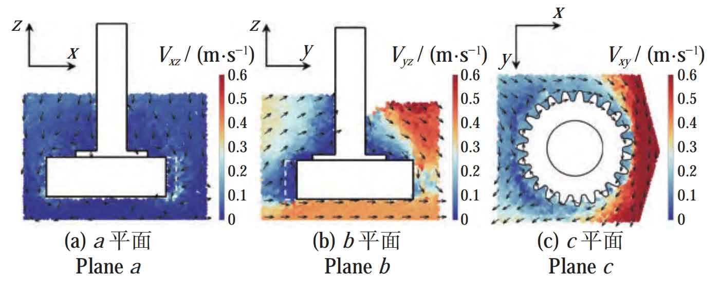
Figure 5a shows the instantaneous velocity cloud map of particles in the xz plane. The velocity of particles in the xz direction is relatively small, and the velocity of particles on the tooth surface and lower end face of spur gears is almost zero. Figure 5b shows the instantaneous velocity cloud map of particles in the yz plane. From the motion of particles in Figure 5b, it can be seen that when the particle swarm impacts the spur gear, due to the obstruction of the spur gear, some particles in the front area of the spur gear begin to move upwards. At this stage, the particle velocity is 0-0.3 m/s. The closer the particles are to the root of the tooth groove, the smaller the particle velocity. When the particles climb to the upper end of the spur gear, the direction of particle motion changes to move along the upper end towards the rear end of the spur gear, and finally flows into the wake area of the spur gear. At this time, the particle velocity rapidly increases, and the particle velocity in the wake area is 0.4-0.6 m/s. It should be pointed out that the particles on the lower end face of the spur gear maintain their original speed and pass quickly through the lower end of the spur gear; Due to the obstruction of the fixture shaft, the upper speed of the spur gear in Figure 5b decreases, while in reality, particles will pass through at a faster speed on both sides of the fixture shaft. Figure 5c shows the velocity cloud map of particles in the xy plane. It can be seen that when the particle swarm impacts the spur gear, not only does it have upward climbing motion in the yz plane, but also a portion of particles will flow towards the left and right sides of the spur gear at a speed of about 0.2 m/s; Due to the clockwise rotation of both the spur gear and the drum in the figure, almost all particles in the front end of the spur gear flow through the spur gear from the right end of the spur gear, which is close to the drum wall. When the particles flow through the right side of the spur gear, due to the lack of obstruction from the spur gear, the particles are subjected to the combined action of the spur gear rotation and drum rotation, rapidly passing through the spur gear at a speed of>0.6 m/s, and finally flowing towards the wake area at the rear end of the spur gear.
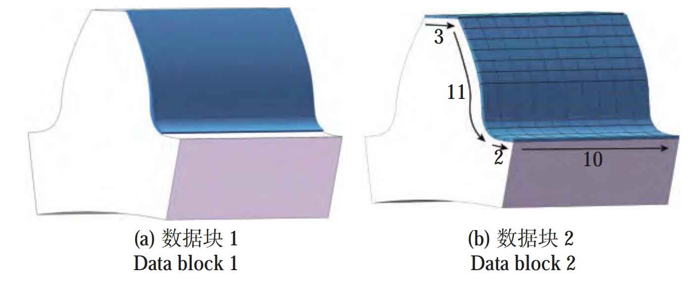
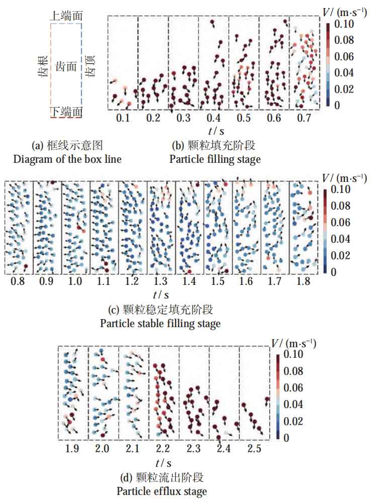
The rotation of drums and gears, as well as the burial depth of spur gears, can affect the flow of particles in spindle type rolling and finishing machining, thereby affecting the machining of spur gears by particles. To explore the interaction mode between particles and particles at the contact interface, it is necessary to extract relevant parameters of the contact particle tooth surface. Figure 6 shows the distribution of data blocks on a single tooth surface. Figure 7 shows the velocity vector diagram of particles relative to the tooth surface within one revolution of a spur cylindrical gear under the working condition of h1=80 mm and n1=30 r/min. The schematic diagram of the dashed box is shown in Figure 7a, where the left side of the dashed box represents the tooth root and the right side represents the tooth top, with a sampling frequency of 10 Hz (the particles in the figure are not the actual particle size). From the motion of particles within one gear rotation cycle, it can be seen that the tooth surface of spur gears can be divided into three stages in one machining cycle, namely the particle filling stage, the particle stable filling stage, and the particle outflow stage. Figure 7b shows the particle filling stage. Due to the rotation of the spur gear, the particles on the tooth surface gradually leave the cavity area at the rear end of the spur gear. The particles around the spur gear are subjected to the interaction of gravity and particle compression, and begin to flow into the tooth groove from the upper end face and tooth top of the spur gear. At this time, the particle velocity is faster, v>0.10 m/s, and the direction of motion is vertical downward. As the particles continue to flow in, they gradually fill the entire tooth slot, and at the same time, their velocity begins to decrease. Figure 7c shows the stable filling stage of particles. It can be clearly seen that as particles accumulate throughout the entire tooth slot, the direction of particle movement begins to change, shifting from vertical downward during the filling stage to upward movement along the tooth plane. This is because when particles fill the tooth slot, the tooth slot is in the frontal impact area between the particles and the spur cylindrical gear, and the particles in the area are blocked by the spur cylindrical gear to climb upwards, driving the particles in the tooth slot to slide upwards, This also results in particles moving faster near the tooth tip than near the tooth root. At this stage, the number of particles in contact with the tooth surface remains basically constant, and the velocity of the particles is relatively small, mostly concentrated at 0.01-0.05 m/s. Figure 7d shows the particle outflow stage, during which the tooth groove is gradually leaving the frontal impact area between the particles and the spur gear. Under the combined action of the centrifugal force and gravity of the spur gear rotation, the particles flow towards the tooth top and the lower end face of the gear, gradually exiting the tooth groove.
3.2 Force analysis of tooth contact particles
Select the contact particles on the tooth surface (i.e. data block in Figure 6a) as the reference object. When h1=80 mm, the number of particle contacts on the tooth surface of the spur gear during one cycle of rotation is shown in Figure 8. When n1=30 r/min, the variation of the normal contact force on the tooth surface of the spur gear over time during one cycle of rotation is shown in Figure 9. From Figures 8 to 9, it can be seen that the change in the number of contact particles on the tooth surface of spur gears is a gradual increase, followed by a constant and then a gradual decrease. However, the change in the number of contact particles on the tooth surface is not the same under different working conditions. When the rotational speed is smaller and the burial depth is shallower, there are fewer particles left in the tooth slot during the particle outflow stage. This is because when the rotational speed is too low, the centrifugal force provided by the spur gear to the particles is smaller. Secondly, when the slower drum speed drives the particles to impact the spur gear, the wake area at the rear end of the spur gear is also smaller, and the particles can be filled into the tooth slot in a timely manner. Although the number of particles in contact with the tooth surface of spur gears may vary due to different parameters, the number of particles in the stable filling stage is roughly the same, all within the range of 30-40; From the perspective of the normal contact force on the tooth surface of spur gears, this difference is particularly significant. The stage of particle inflow is from 0 to 0.3 T. Although the number of particles in contact with the tooth surface of the spur gear increases rapidly during this stage, the increase in normal contact force on the tooth surface of the spur gear lags behind. It only increases significantly when the number of particles in contact reaches 30, and the normal contact force is almost zero for most of the time. The period of 0.3-0.7 T is the stage of stable particle filling, during which the normal contact force on the tooth surface of the spur gear increases rapidly in a short period of time, and then maintains a relatively large normal contact force until the particles begin to rapidly flow out of the tooth groove. 0.7-1.0 T is the stage of particle outflow, during which the normal contact force on the tooth surface of the spur gear decreases rapidly and approaches 0 for most of the time. Under the five operating conditions set in the discrete element simulation, the average normal contact force on the tooth surface of the spur gear during the stable filling stage of particles is 22.45 times that of the particle inflow stage and 26.24 times that of the particle outflow stage. This indicates that the stable filling stage is the main stage for particles to act on the spur gear.
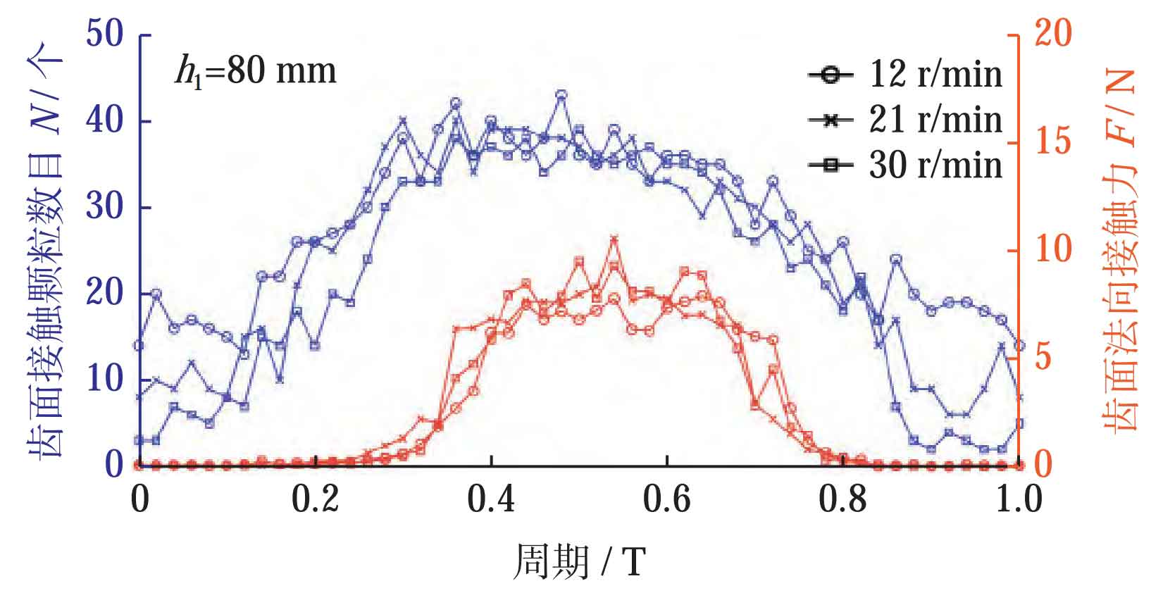
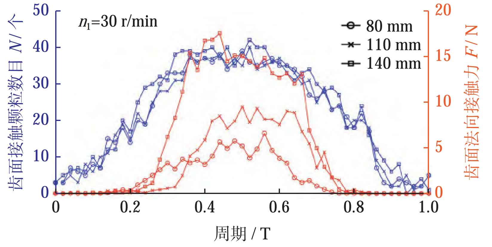
From Figure 8, it can be seen that as the speed increases, the normal contact force on the tooth surface of the spur gear slightly increases, with a small difference. When the speed increases by 150% from 12 r/min to 30 r/min, the normal contact force on the tooth surface increases by 18%. From Figure 9, it can be seen that as the burial depth increases, the normal contact force on the tooth surface of the spur gear significantly increases. When the burial depth increases by 75% from 80 mm to 140 mm, the normal contact force on the tooth surface of the spur gear increases by 76%. Therefore, it can be explained that the force of particles on the tooth surface is greatly affected by the depth of gear embedding, and is less affected by the speed.
To explore the distribution of contact force on the tooth surface of spur gears, it is necessary to extract the average normal contact force in different areas of the tooth surface during one cycle of gear rotation. Divide 10 data blocks equally along the axial direction of the spur gear, and divide 3, 11, and 2 data blocks along the tooth profile of the spur gear on the tooth top surface, tooth surface, and tooth groove bottom surface, respectively (the area of the data blocks on the tooth surface and tooth top surface is different, corrected by multiplying the area ratio coefficient), as shown in Figure 6b. Figure 10 shows the variation cloud map of the normal contact force on the gear surface under different drum speeds and burial depths of spur cylindrical gears at h1=80 mm and n1=30 r/min. From Figure 10, it can be seen that particles can almost act on all areas of the tooth surface of the spur gear. There is a significant force on the main meshing area of the spur gear near the indexing circle, but there is also a significant uneven distribution of the normal contact force on the tooth surface. The normal contact force from the tooth root to the tooth top gradually increases, and there is also a significant difference in the normal contact force between the upper and lower tooth surfaces. This is due to the semi-closed structure of the tooth groove. When there are many particles in the tooth groove, they will compress and friction with themselves and the tooth surface, causing the impact force carried by the particle group to gradually dissipate. The force on the tooth surface closer to the bottom of the tooth groove (tooth root) is smaller, ultimately leading to uneven force distribution from the tooth root to the tooth top.
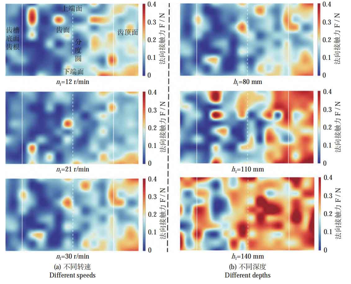
In the five simulated working conditions, the average normal contact force on the upper tooth surface is 1.52-1.88 times that on the lower tooth surface. It can be seen that there is a significant difference in force on the upper and lower tooth surfaces, but the effect of changing the drum speed and gear embedding depth on this difference is not significant. At the same time, it can also be seen that there is uneven force distribution on the tooth surface along the axial direction. Taking the axial center plane of the spur gear as the interface, the tooth surface near the lower end face is 1.15-1.01 times that near the upper end face; And as the burial depth increases, the difference between the two significantly decreases, especially when the burial depth is 140 mm and tends to be the same. Therefore, in actual machining, the method of increasing the burial depth can be used to reduce the machining differences along the axial direction of spur gears.
3.3 Analysis of particle velocity in contact
As can be seen from the above, the main action stage of particles on the tooth surface of spur gears is the stable filling stage. Therefore, the particles in contact with the tooth surface in this stage are selected as the reference object (0.4 gear rotation cycles) to explore the influence of rotational speed and burial depth on the relative motion speed of particles. Figure 11 shows the variation of particle velocity relative to the tooth surface during the stable filling stage. Figure 11a shows the variation of average relative velocity of particles at different rotational speeds when the workpiece is buried at a depth of h1=80 mm. From Figure 11a, it can be seen that as the rotational speed increases, the average relative velocity of particles in different areas of the tooth surface increases linearly, increasing by 148% to 151% from 12-30 r/min, with the tooth surface increasing by 148%; It can also be seen that due to the influence of the tooth groove structure of spur gears, the average relative velocity of particles on the upper tooth surface is significantly higher than that on the lower tooth surface. At different speeds, the upper tooth surface is 1.35-1.40 times that of the lower tooth surface. Figure 11b shows the variation of the average relative velocity of particles at different depths when the drum speed is n1=30 r/min. It can be seen that as the depth of the workpiece burial increases, the average relative velocity of particles does not increase significantly. The different areas of the tooth surface of the spur gear increase by 2% to 9% at 80-140 mm, and the middle tooth surface increases by 4%. The difference between the upper and lower tooth surfaces still exists; At different burial depths, the upper tooth surface is 1.35-1.45 times the lower tooth surface.
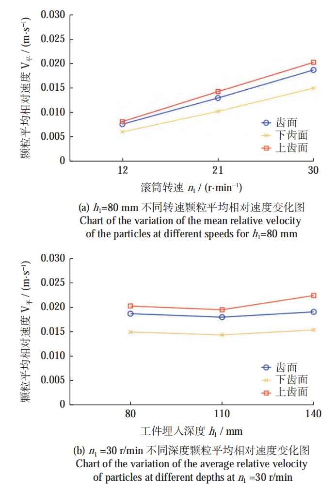
Therefore, it can be explained that the relative velocity between particles and tooth surfaces is less affected by the depth of gear embedding, and is more affected by rotational speed. There is an uneven phenomenon on the upper and lower tooth surfaces of spur cylindrical gears, and the average relative velocity of particles on the upper tooth surface is 1.35-1.45 times that on the lower tooth surface. Changing the rotational speed and the depth of workpiece embedding has a smaller impact on this uneven phenomenon. Based on Section 3.2, it can be concluded that increasing depth mainly affects the contact force between particles and tooth surfaces, while increasing rotational speed mainly affects the relative motion speed between tooth surfaces and particles.
4. Validity verification
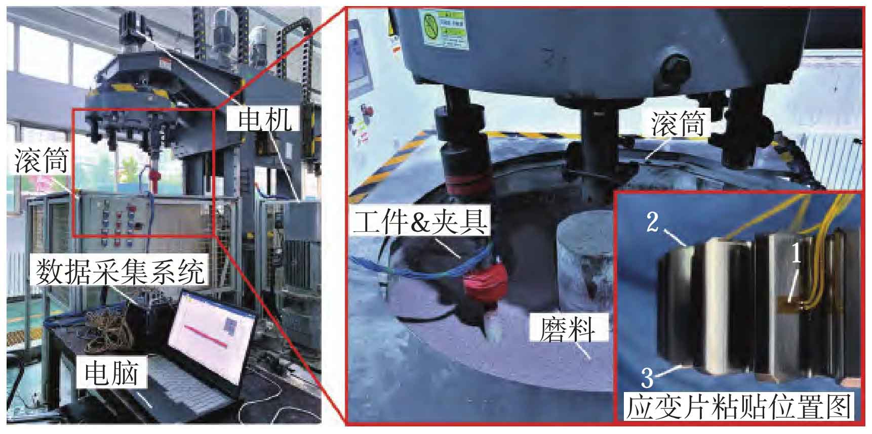
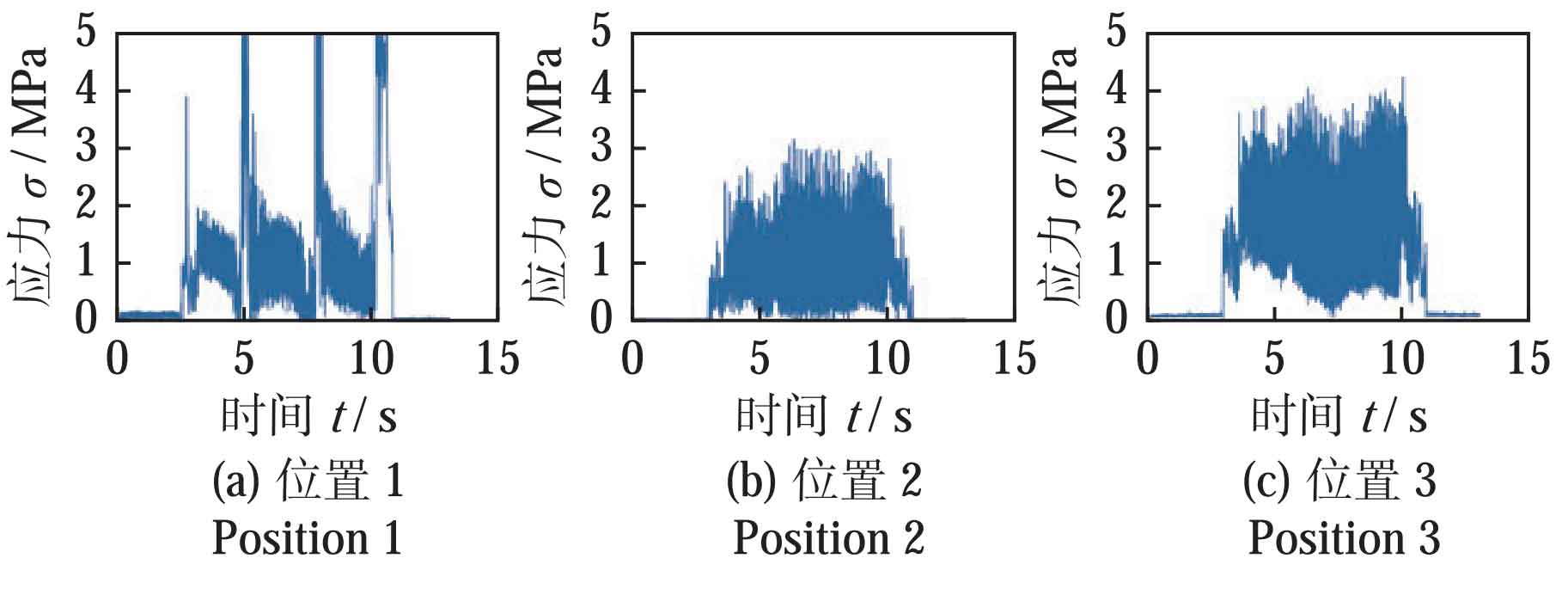
To verify the effectiveness of simulation analysis, a strain testing experimental platform for spindle type rolling and finishing of spur cylindrical gears was built based on the X1400 swirl vertical free grinding machine. As shown in Figure 12, the platform consists of a DH5903N robust dynamic signal testing and analysis system, strain gauges, motors, drums, fixtures, workpieces, and computers. Stick one resistance strain gauge (BX120-10AA) at each of the three positions on the tooth surface, upper end face, and lower end face. The burial depth and speed settings are consistent with the simulation. The sampling frequency is 10 kHz, and two tests are conducted under each operating condition. The spur gear undergoes deformation under the action of particles, and the deformation is transmitted to the strain gauge attached to the spur gear. The strain data collected by the strain gauge is used to characterize the effect of particles on the tooth surface. When the strain gauge is compressed, the resistance decreases and the output is negative. Due to the discrete impact of particle interactions, there will be positive and negative fluctuations in strain. Therefore, set the positive value of the output stress to 0, retain only the negative signal, and apply a 200 Hz low-pass filter to the signal to remove drift. Figure 13 shows the stress changes at positions 1, 2, and 3 at h1=80 mm and n1=30 r/min. From Figure 13, it can be seen that the stress at position 1 undergoes periodic changes with the rotation of the spur gear, while there is no periodic change at positions 2 and 3, which is consistent with the discrete element simulation analysis. At the same time, the stress at position 3 is significantly greater than that at position 2, indicating that the force acting on the lower end face of the spur gear is greater than that on the upper end face. There is uneven machining on the upper and lower end faces, which is consistent with the conclusion of discrete element simulation.
Select the average stress values tested at three locations within one week and the simulated average normal contact force as the research objects. The changes in depth and speed are shown in Figure 14, where the bar graph represents stress and the line graph represents normal contact force.
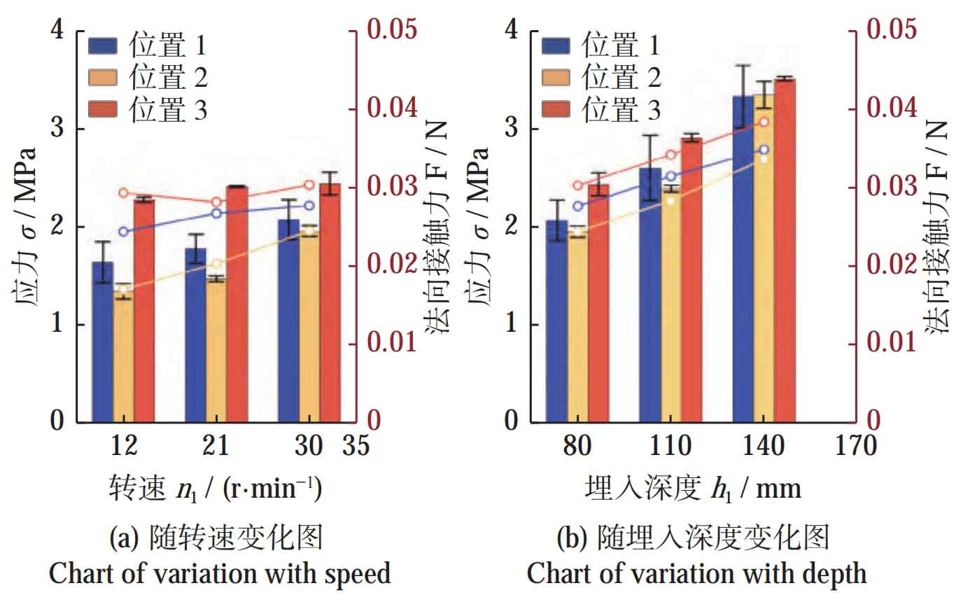
Figure 14a shows the variation of stress and normal contact force at three positions with rotational speed when h1=80 mm. From Figure 14a, it can be seen that the stress and normal contact force increase slightly with the increase of rotational speed, and the trend of their changes is the same. When the rotational speed increases by 1.5 times, the stress at the three positions increases by 17%, 28%, and 17% respectively, and the normal contact force increases by 14%, 26%, and 5%, respectively. Figure 14b shows the variation of stress and normal contact force at three positions with burial depth at n1=30 r/min. From Figure 14b, it can be seen that the stress and normal contact force increase significantly with the increase of rotational speed, and their changing trends are the same. When the burial depth increases by 75%, the stress at three positions increases by 59%, 35%, and 43% respectively, and the normal contact force increases by 32%, 40%, and 34%, respectively. Therefore, it can be concluded that depth is the main factor affecting the force exerted by particles on spur gears, which is consistent with the conclusions obtained from discrete element simulation, thus verifying the effectiveness of the simulation.
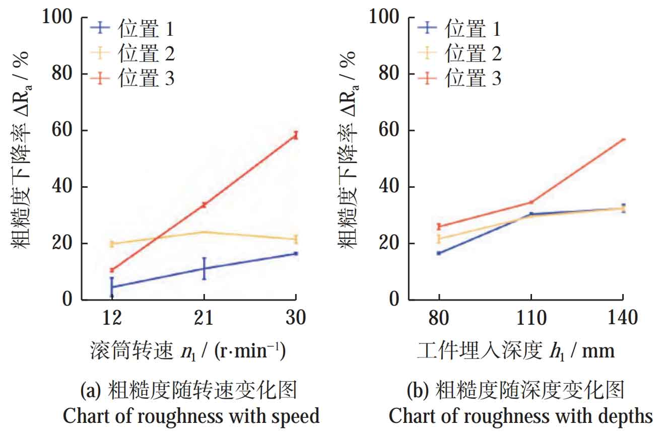
At the same time, in order to further analyze the influence of depth and speed on the machining effect of spur cylindrical gears, experiments were conducted to test the changes in roughness Ra before and after machining of spur cylindrical gears at positions 1, 2, and 3 under different experimental parameters. The experimental parameters were consistent with the above, and each group had a machining time of 2 hours. Figure 15a shows the variation of roughness reduction rate at three positions with drum speed n1 when h1=80 mm. From Figure 15, it can be seen that with the increase of rotational speed, the roughness reduction rate at three positions has significantly improved. Among them, the decrease in the lower end face (position 3) of the spur gear is the most significant, reaching 58.36% at n1=30 r/min, which is 5.36 times higher than that at n1=12 r/min. Figure 15b shows the variation of roughness reduction rate at three positions with burial depth h1 at n1=30 r/min. From Figure 15b, it can be seen that the roughness reduction rate at three positions increases with the increase of burial depth. Similarly, the roughness reduction at the lower end face of the spur gear is most significant, reaching 56.89% at h1=140 mm, which is 2.03 times higher than that at h1=80 mm.
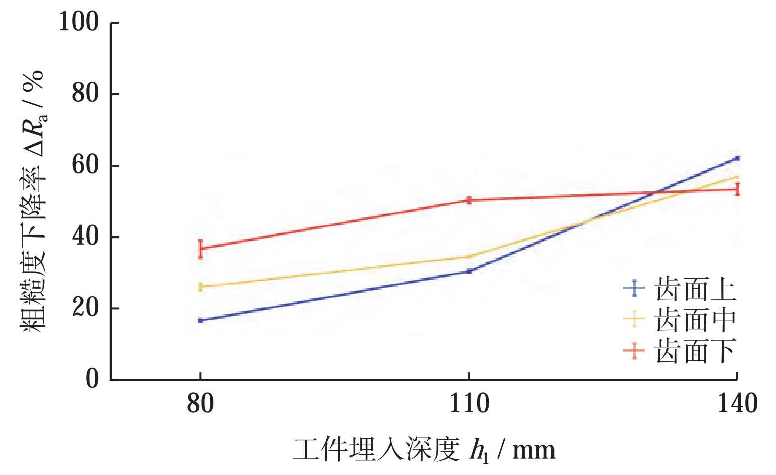
In addition, the influence of embedding depth on the uniformity of machining along the axial direction of spur cylindrical gears was analyzed. Figure 16 shows the variation of tooth surface roughness at different depths. As shown in Figure 12, three regions were selected along the gear axis on the tooth surface: the upper, middle, and lower parts of the tooth surface. The variation of the roughness reduction rate of these three regions with the burial depth h1 was investigated when n1=30 r/min. From Figure 16, it can be seen that when the burial depth is lower than 80 mm, the roughness reduction rates in the three regions are 17%, 26%, and 36%, respectively. The roughness reduction rate in the upper region of the tooth surface is significantly lower than that in the lower region; When the depth reaches 140 mm, the roughness reduction rates of the three regions are 62%, 58%, and 55%, respectively. The roughness reduction rates of the tooth surface are basically the same, which is consistent with the conclusion drawn in the simulation that increasing the burial depth can reduce the axial force difference of spur gears, thus proving the effectiveness of the simulation.
5. Conclusion
For spindle rolling and finishing machining, the discrete element simulation method was used to describe the flow characteristics of the entire particle group and the contact particles on the tooth surface during spindle rolling and finishing machining. The effects of depth and speed on the relative velocity and contact force of the contact particles on the tooth surface were analyzed. Finally, the following conclusions were drawn through experimental verification:
(1) The particle flow and force inside the groove of a spur gear exhibit periodic changes, which can be divided into three stages: particle filling stage, particle stable filling stage, and particle outflow stage. Among them, the particle stable filling stage is the main stage in which particles act on the spur gear. The average normal contact force on the tooth surface during the stable filling stage is 22.45 times that of the particle filling stage and 26.24 times that of the particle outflow stage.
(2) The increase in burial depth of spur gears mainly affects the contact force between particles and tooth surfaces. When the burial depth increases by 75%, the normal contact force on the tooth surface of spur gears increases by 76%, and the relative motion speed between particles and tooth surfaces increases by 4%; The increase in speed between spur gear and drum mainly affects the relative motion speed between particles and tooth surfaces. When the speed between spur gear and drum increases by 150%, the relative motion speed of particles in contact with the tooth surface increases by 148%, and the normal contact force on the tooth surface increases by 18%.