
Cylindrical gear transmission is one of the most widely used power transmission mechanisms. In cylindrical gear transmission, due to manufacturing and installation errors, as well as elastic deformation, the load is unevenly distributed along the tooth width direction, resulting in adverse phenomena such as meshing misalignment, meshing impact, and noise, which can easily cause local tooth breakage of cylindrical gears. The tooth profile modification can obtain drum shaped gear teeth, which can evenly distribute stress during the meshing of cylindrical gears, reduce meshing bias load, and make tooth wear uniform, reduce vibration and noise during the meshing transmission process of cylindrical gears, and improve the meshing transmission performance of cylindrical gears.
In terms of tooth profile modification, Han J et al. proposed using high-order polynomial form to perform topological modification on cylindrical gears on machine tools; Wang Shaojie et al. proposed using multi axis linkage on the honing wheel to perform tooth profile modification machining on cylindrical gears. Yu T et al. proposed a method for modifying cylindrical gears by using diamond dressing wheels with the same tooth surface as the target cylindrical gear; Jiang Jinke et al. proposed the use of conical grinding wheel axial stroke point contact edge grinding for gear shaping cutters and topological modification of cylindrical gear tooth surface gear shaping correction methods; Yang Hui et al. established a mathematical model for shaping and grinding tooth profile modification based on the principle of spatial meshing, and verified the correctness of the model through helical drum shaped modified cylindrical gears.
When using cylindrical gear grinding technology for tooth profile modification, the motion is complex and the accuracy is difficult to ensure; The grinding wheel needs to move along the tooth width direction, resulting in lower grinding efficiency. In order to improve the efficiency and accuracy of cylindrical gear grinding and tooth profile modification, ZHY Gear proposed a new grinding method that can achieve tooth profile modification, and verified this method through simulation using Vericut. At the same time, the meshing characteristics of the simulated cylindrical gear were analyzed, and a control method for drum shape was provided.
1. Principle of oblique installation grinding disc for gear grinding
1.1 Principle of generating teeth with butterfly shaped grinding wheel
At present, the main method for grinding teeth is to use a butterfly shaped grinding wheel to grind the tooth surface, and the grinding principle is shown in Figure 1. To grind the involute tooth profile, the tooth blank needs to undergo generating motion, i.e. V= ω· r. Where V is the speed of tooth blank movement, ω Is the speed of the gear blank, and r is the radius of the indexing circle. Grinding wheel according to angular velocity ω When T rotates, the grinding wheel forms a grinding plane to grind the tooth surface. At this time, the grinding wheel moves in a straight line along the axis of the tooth blank, which is intermittent machining in the tooth width direction. The grinding efficiency of cylindrical gears is low, which affects the grinding accuracy.
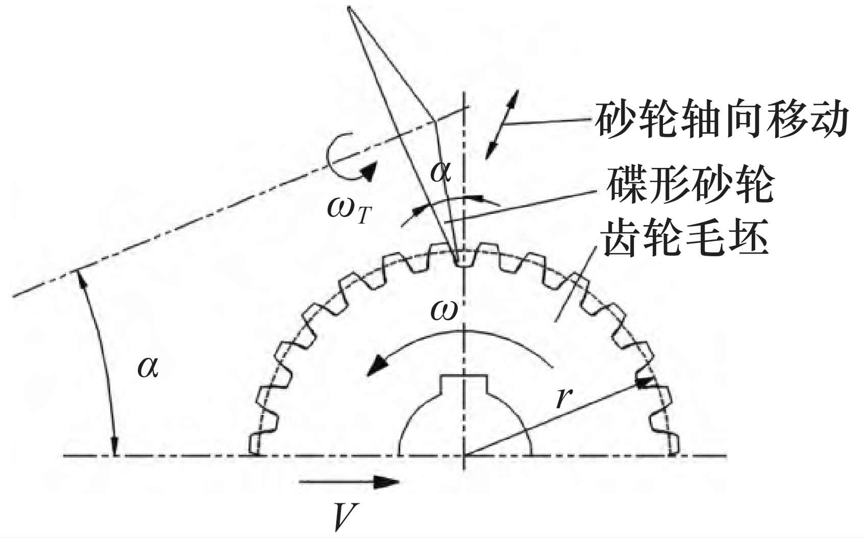
When using the above-mentioned gear grinding method for tooth profile modification, the grinding wheel needs to make additional motion along the cylindrical gear, the motion trajectory is complex, the control of the modification amount is difficult, and high precision is required for the machine tool.
1.2 Principle of oblique installation of grinding disc for grinding teeth
A new grinding method for cylindrical gears using oblique mounting grinding discs is proposed based on the problems of generating grinding with butterfly shaped grinding wheels. The tooth surface is ground with full tooth width by sintering cubic boron carbide on the grinding disc, and the installation angle of the grinding disc is θ, The radius of the grinding disc is R, and it can be adjusted according to the required tooth profile modification to grind cylindrical gears suitable for different occasions. The principle of cylindrical gear grinding is shown in Figure 2. By adjusting the grinding disc, the contact angle between the grinding disc and the tooth surface is ensured to be the pressure angle of the cylindrical gear α。 To grind the involute tooth profile, the tooth blank also needs to undergo generating motion, i.e. VXc= ω C · r, where VXc is the speed of tooth blank movement, ω C is the speed of the gear blank, and r is the radius of the indexing circle.
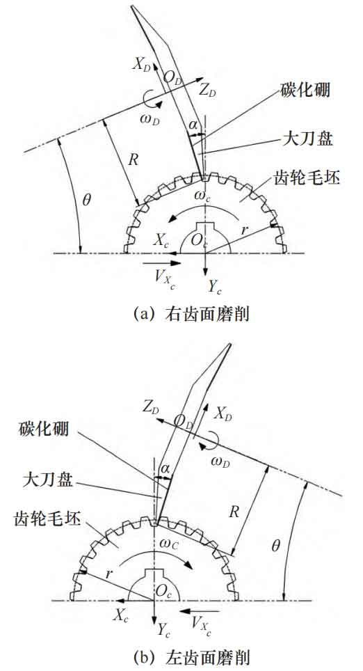
When installing the angle of the grinding disc θ > α , The grinding trajectory is a conical surface, and the full tooth width is used to grind the tooth surface, forming micro drum teeth and achieving tooth profile modification; When installing the angle of the grinding disc θ = α, If the grinding trajectory is flat, it is impossible to achieve tooth profile modification. When grinding, ensure that the centerline of the tooth width of the blank is at the same height as the center of the grinding disc, and the machined micro drum gear tooth surface of the cylindrical gear will be a symmetrical micro drum shape. Otherwise, the tooth surface will be an asymmetric micro drum shape.
2. Oblique installation grinding disc gear grinding device and simulation
2.1 Model of oblique installation grinding disc gear grinding device
Figure 3 shows a grinding device for grinding the right tooth surface of a cylindrical gear, which achieves generative grinding through a indexing turntable and a longitudinal slide rail. When grinding the left tooth surface, the grinding disc needs to be symmetrically placed.
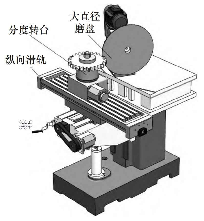
Based on the parameters in Table 1, use SolidWorks to establish a model of the cylindrical gear blank and machining device, and import it into Vericut. During machining, rotate the sintered boron carbide on the grinding disc to form a grinding cone surface, in order to grind out micro drum shaped cylindrical gears.
| Number of teeth | 36 | Modulus | 5 |
| Pressure angle α/ (°) | 20 | Tooth width B/mm | 30 |
| h*a tooth top height coefficient | 1 | Top clearance coefficient C* | 0.25 |
| Grinding disc radius RT/mm | 500 | Grinding disc installation angle θ/ (°) | 20.3 |
2.2 Processing simulation
After setting the machining parameters reasonably, import the CNC program for simulation machining of cylindrical gears. During the machining process, the grinding disc rotates rapidly to produce micro convex tooth surfaces, as shown in Figure 4.
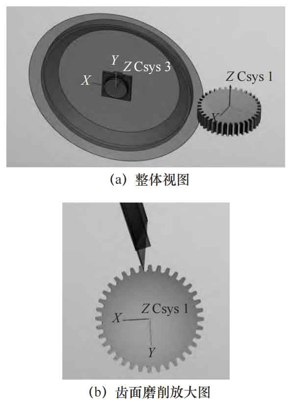
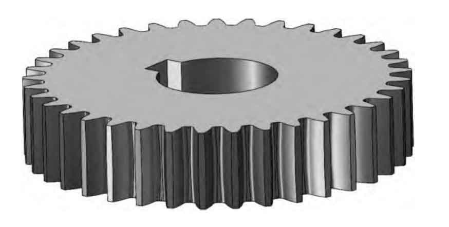
After processing and simulation, the micro drum gear tooth cylindrical gear was obtained, and after export, it is shown in Figure 5. When the center line of the tooth width of the blank is at the same height as the center of the grinding disc, the tooth surface after grinding is a symmetrical micro drum shape, and the tooth thickness at the center line of the tooth width is slightly greater than the tooth thickness at the end face of the cylindrical gear, forming a micro drum shaped tooth.
Due to the change in the distance between the tool and the center of the gear blank in the radial direction during the machining of cylindrical gears, the tooth groove is in a state of deep in the middle and shallow at both ends, resulting in a depth difference σ For:
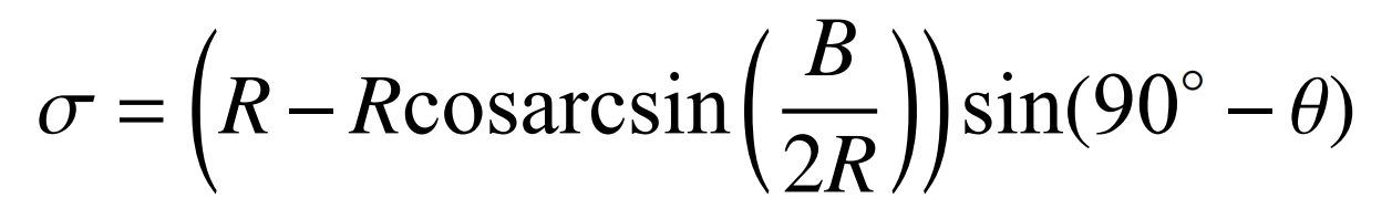
When the tooth width B=30 mm, the tool tip trajectory radius R=500 mm, and the grinding disc installation angle, the depth difference is 0.211 mm, and its impact on the meshing of cylindrical gears can be ignored.
3. Simulation model analysis
In order to obtain the contact characteristics of the cylindrical gear after grinding, the meshing characteristics of the cylindrical gear after grinding are analyzed. Accurately assemble cylindrical gear pairs in SolidWorks based on their meshing conditions, and use interference inspection tools to perform interference analysis on the tooth surfaces of cylindrical gear pairs, as shown in Figure 6.
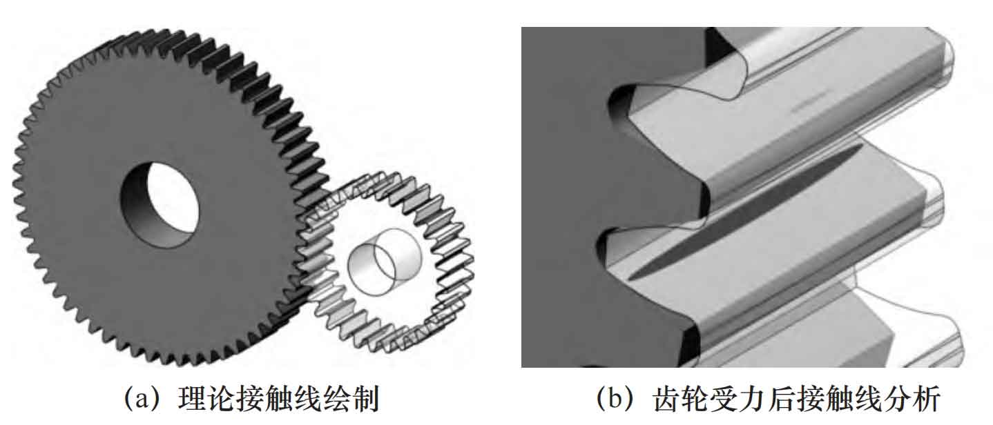
The analysis results show that the contact area of the drum shaped cylindrical gear is mainly in the middle part, and the stress in the middle of the tooth surface is greater than the stress at the tooth end. This can effectively improve the uneven load distribution along the tooth width direction caused by errors, elastic deformation, and other reasons during cylindrical gear transmission, effectively reduce the bending stress at the tooth roots at both ends of the cylindrical gear, reduce the meshing offset load of the cylindrical gear, improve the meshing performance of the cylindrical gear, reduce the transmission noise of the cylindrical gear, and enhance the bearing capacity of the cylindrical gear.
4. Calculation and control method for the drum shape of cylindrical gears with tooth profile modification
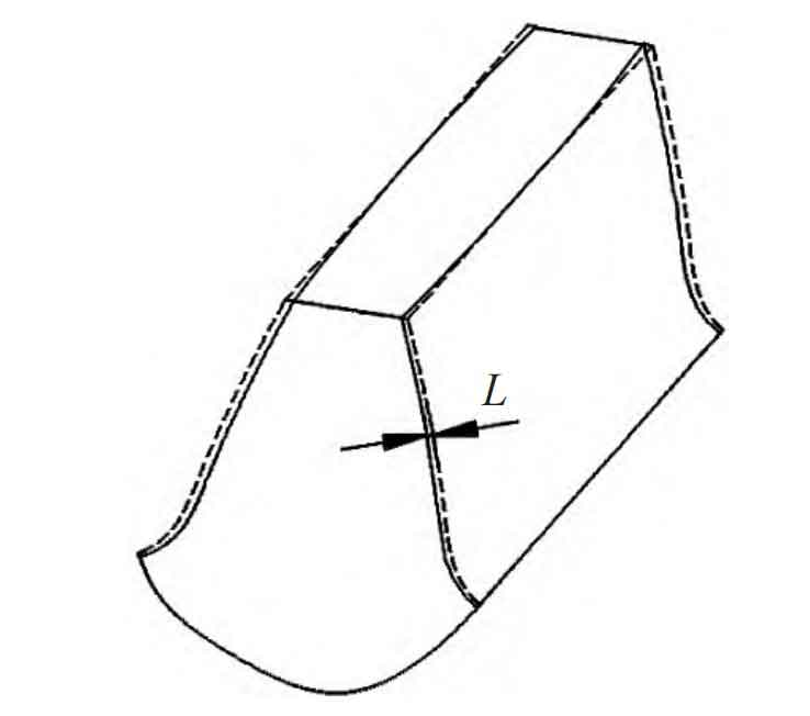
The drum shape of cylindrical gears after tooth alignment modification is the basis for analyzing the meshing characteristics, transmission performance, and anti offset load capacity of cylindrical gears, as shown in Figure 7. The drum shape of cylindrical gears after grinding is L.
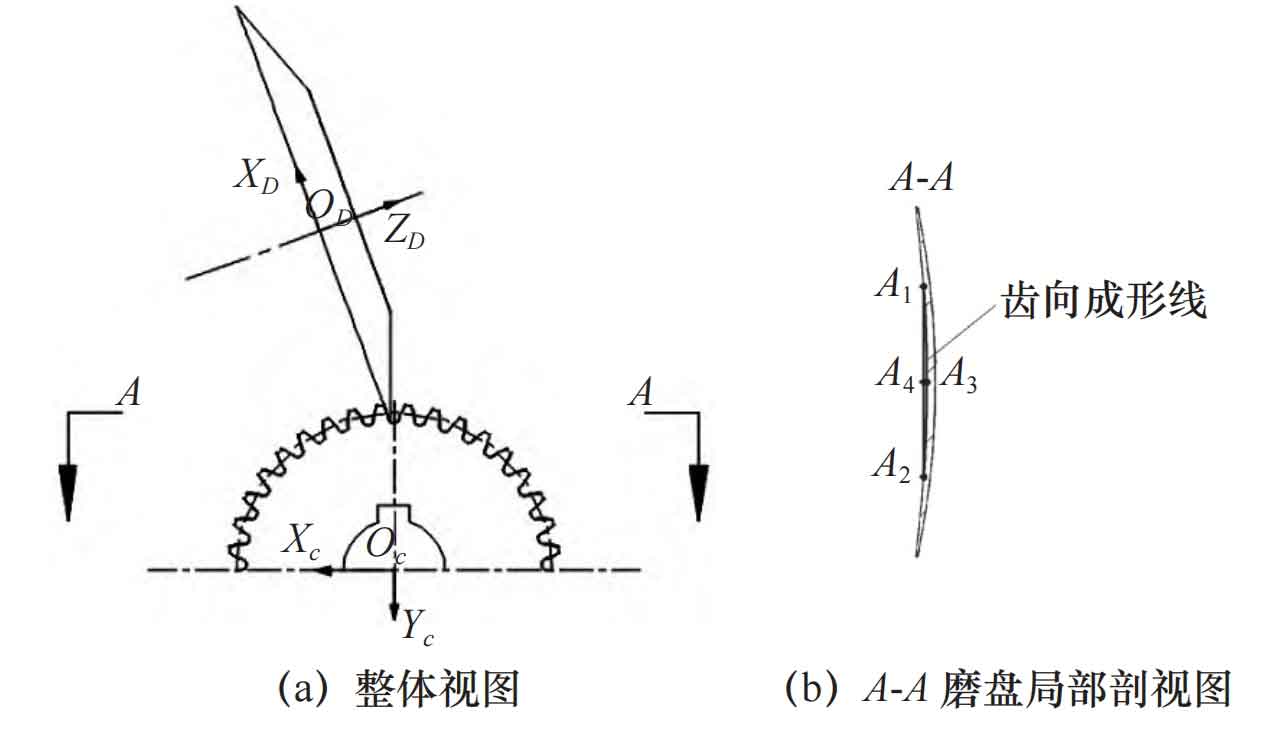
The grinding trajectory of the grinding disc during machining is a conical surface, as shown in Figure 8. The intersection line between the circular cutting plane of the cylindrical gear and the grinding conical surface within the tooth width range is arc A1A2. The midpoint of arc A1A2 is A3, and the distance from the midpoint A4 of segment A1A2 is the drum shape. The ZD axis of the coordinate system SD (ODXDYDZD) passes through the center of the grinding disc, and the equation for the conical surface formed by the blade trajectory in the coordinate system SD is:
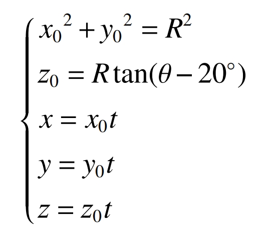
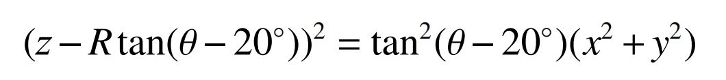
Removing parameter t yields:
The tangent plane of the cylindrical gear pitch circle is parallel to the YD axis and tangent to the tool pitch plane. Its equation in the coordinate system SD is:
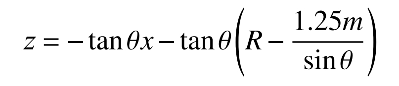
The equation for the intersection line between the grinding cone surface and the tangent plane of the cylindrical gear pitch circle is:
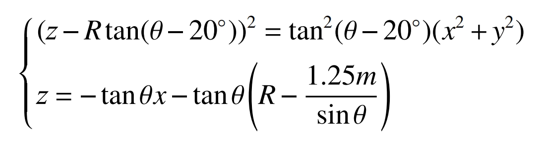
The equation for the line segment A1A2 in the coordinate system is:
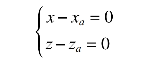
The midpoint of line segment A1A2 is A4 (xa, 0, za), and the coordinates of the midpoint of the intersection line with the grinding cone surface and the tangent plane of the cylindrical gear pitch circle within the tooth width range are A3 (xb, 0, zb). Therefore, the drum shape of the cylindrical gear is:
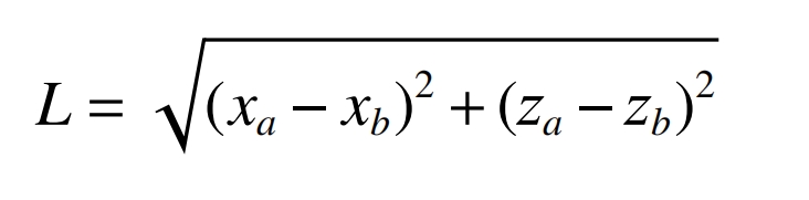
Substituting y=B/2 and y=0 into equation (5) yields Xa, Za, and Xb, Zb, respectively.
By using equation (5) and Matlab, the grinding cone surface and the cylindrical gear pitch circle cutting plane are respectively established in a three-dimensional coordinate system, as shown in Figure 9. The intersection line can be obtained as an elliptical arc by tilting the pitch circle cutting plane of the cylindrical gear on the axis of the grinding cone surface.
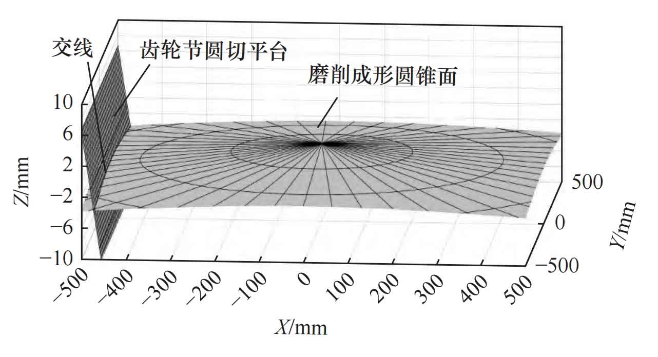
From equation (5), it can be seen that the drum shape of the cylindrical gear after grinding is determined by the gear module m, tooth width B, and the installation angle of the grinding disc inclination θ 、 The radius R of the grinding disc is controlled, and the drum shape can be controlled by adjusting the installation angle of the grinding disc during actual machining of cylindrical gears with different parameters, θ The larger the drum shape, the greater the quantity. When the module of the cylindrical gear is m=5, the tooth width is B=30 mm, and the tool tip trajectory radius is R=500 mm, change the installation angle of the grinding disc through equations (5) and (7) θ A series of drum shapes can be obtained, as shown in Table 2.
| Grinding disc installation angle θ/ (°) | Drum shape measurement L/mm |
| 20.50 | 0.0217 |
| 20.45 | 0.0195 |
| 20.40 | 0.0173 |
| 20.35 | 0.0151 |
| 20.30 | 0.0129 |
| 20.25 | 0.0107 |
| 20.20 | 0.0085 |
| 20.15 | 0.0064 |
| 20.10 | 0.0042 |
| 20.05 | 0.0021 |
| 20.00 | 0 |
In Table 2, when the installation angle of the grinding disc θ As it gradually increases, the drum shape of the cylindrical gear gradually decreases. When the installation angle of the grinding disc is set, the drum shape is 0, which means that the processed gear is a standard straight tooth cylindrical gear, which conforms to the above grinding processing principle and verifies the accuracy of the drum shape calculation.
5. Conclusion
ZHY Gear first proposed the method of using an inclined grinding disc to grind cylindrical gears. Based on the grinding principle, a simulation model of the machining device was established, and the machining simulation of the cylindrical gears was achieved using Vericut. The meshing characteristics of the simulated cylindrical gears were analyzed, and a control method for the drum shape was proposed. The following conclusions were obtained:
(1) A method of grinding cylindrical gears using a slanted installation grinding disc is proposed. By sintering boron carbide on the slanted installation grinding disc, the cylindrical gears are ground with full tooth width, effectively improving the grinding efficiency of the cylindrical gears while achieving tooth profile modification. The depth in the middle of the tooth groove is slightly greater than the depth of the two end grooves. When the cylindrical gear pair is meshed after grinding, the contact area is mainly in the middle area of the tooth surface, with less contact at both ends, effectively reducing the bending stress at the tooth roots at both ends of the cylindrical gear and reducing gear meshing offset load.
(2) The control method for the drum shape during grinding cylindrical gears is provided, which is determined by the installation angle of the grinding disc θ , The module m, tooth width B, and grinding disc radius R of cylindrical gears are determined by adjusting the installation angle of the grinding disc during actual machining θ Realize the adjustment of the drum shape of the gear teeth.