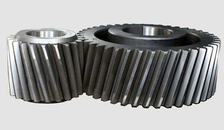
Designing a helical gear in CAD (Computer-Aided Design) software is a critical step in the gear manufacturing process, allowing engineers and designers to precisely model the geometry and specifications of the helical gear before production. This process involves several key stages, from defining the initial parameters to refining the helical gear design for optimal performance. Here’s a step-by-step guide to designing a helical gear in CAD, emphasizing the integration of engineering principles with modern design tools.

Step 1: Define Gear Specifications
- Determine Application Requirements: Consider the load, speed, power transmission requirements, and the operating environment to define the helical gear size, material, helix angle, and gear ratio.
- Select Material: Based on the application, choose a material that offers the required strength, durability, and wear resistance. Material selection will influence the helical gear’s performance and lifespan.
Step 2: Calculate Gear Dimensions
- Module or Diametral Pitch: Decide on the module (metric system) or diametral pitch (imperial system) based on the application. This will determine the size of the teeth.
- Number of Teeth: Calculate the number of teeth needed to achieve the desired helical gear ratio and size.
- Helix Angle: Select a helix angle that balances the benefits of smooth operation and high load capacity with the challenge of axial thrust.
- Face Width: Determine the appropriate face width for the helical gear, considering the load it will carry and the material selected.
Step 3: Model the Gear Tooth Profile
- Draw the Involute Curve: Using the CAD software, draw the involute curve that defines the tooth profile. This curve is crucial for ensuring smooth engagement and efficient power transmission.
- Define the Helix: Model the helical path of the helical gear teeth around the helical gear body using the previously determined helix angle.
- Apply Tooth Modifications: If necessary, apply profile shifting or other modifications to optimize the helical gear’s performance for specific conditions, such as minimizing backlash or reducing stress concentrations.
Step 4: Create the Gear Body
- Sketch the Gear Blank: Model helical gear blank, ensuring it’s appropriately sized to accommodate the teeth and any necessary hubs or bores for mounting.
- Extrude the Gear Teeth: Use the CAD software’s tools to extrude helical gear teeth along the helical path around helical gear blank. This will create the three-dimensional shape of the gear.
- Add Features: Include any additional features, such as keyways, fillets, or custom hubs, that are required for helical gear’s application or assembly.
Step 5: Refine and Analyze
- Mesh Analysis: Perform a mesh analysis to check helical gear’s strength and identify any potential areas of weakness.
- Kinematic Simulation: Use the CAD software’s simulation capabilities to analyze helical gear’s operation, including meshing with mating gears and the resulting forces and motion.
- Adjustments: Based on the analysis, make any necessary adjustments to helical gear’s design to improve its performance or manufacturability.
Step 6: Prepare for Manufacturing
- Generate Technical Drawings: Create detailed technical drawings that include all critical dimensions, tolerances, and surface finish requirements.
- Select Manufacturing Process: Based on helical gear’s design and material, choose the appropriate manufacturing process (e.g., hobbing, shaping, milling) and prepare any necessary CAM (Computer-Aided Manufacturing) files.
Step 7: Prototyping and Testing
- Create a Prototype: If possible, manufacture a prototype of helical gear to test its real-world performance.
- Testing and Evaluation: Conduct testing to evaluate helical gear’s performance under operational conditions. Adjust the CAD model as necessary based on the results.
Designing a helical gear in CAD is a comprehensive process that combines engineering principles with digital modeling techniques. By following these steps, designers can create precise, efficient, and reliable gears tailored to their specific application needs. Advances in CAD software and integration with CAM processes have streamlined the transition from concept to creation, enabling more complex and innovative helical gear designs.
