
Finite Element Analysis (FEA) is a powerful computational tool used extensively in the design and optimization of straight bevel gear. This advanced simulation technique allows engineers to analyze the behavior of straight bevel gear components under various operating conditions, thereby enhancing their performance, durability, and reliability. This article delves into the application of finite element analysis in the design and optimization of straight bevel gear, highlighting its benefits, methodologies, and practical implications.
Introduction
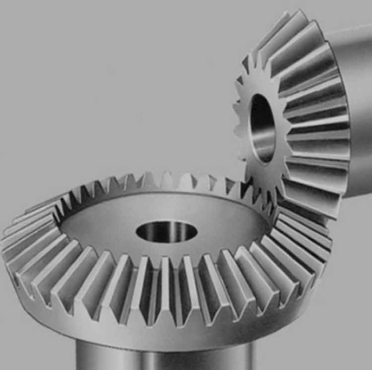
Straight bevel gear is integral components in many mechanical systems, used to transmit power between intersecting shafts at various angles. Their design and optimization are critical to ensure efficient operation and longevity. Finite Element Analysis (FEA) provides a detailed insight into the stress distribution, deformation, and potential failure points within straight bevel gear, enabling more accurate and reliable designs.
Benefits of Using Finite Element Analysis in Gear Design
The application of finite element analysis in the design of straight bevel gear offers several benefits:
- Accurate Stress Analysis: Finite element analysis allows for precise calculation of stress distribution within straight bevel gear teeth and body, identifying areas of high stress concentration.
- Predictive Failure Analysis: It helps predict potential failure points and modes, enabling proactive design modifications.
- Optimization of Material Usage: By understanding stress and deformation patterns, material usage can be optimized, leading to cost savings and weight reduction.
- Enhanced Design Flexibility: Finite element analysis facilitates the exploration of various design iterations quickly and efficiently, enhancing overall design flexibility.
Methodologies in Finite Element Analysis for Gear Design
The process of applying finite element analysis in the design and optimization of straight bevel gear involves several key steps:
- Modeling: Creating a detailed 3D model of straight bevel gear, including all geometric features and material properties.
- Meshing: Dividing the model into smaller, finite elements that can be analyzed individually.
- Boundary Conditions: Defining the operating conditions, such as loads, constraints, and environmental factors.
- Simulation: Running the finite element analysis simulation to calculate stress, strain, and deformation under the defined conditions.
- Analysis: Interpreting the results to identify critical areas and potential improvements.
- Optimization: Iteratively refining the design based on the analysis results to achieve optimal performance.
Table 1: Key Steps in Finite Element Analysis for Gear Design
| Step | Description |
|---|---|
| Modeling | Creating a detailed 3D model of straight bevel gear |
| Meshing | Dividing the model into smaller, finite elements |
| Boundary Conditions | Defining loads, constraints, and environmental factors |
| Simulation | Running the finite element analysis simulation to calculate stress and strain |
| Analysis | Interpreting results to identify critical areas |
| Optimization | Refining the design based on analysis results |
Practical Applications of Finite Element Analysis in Gear Design
Finite element analysis is applied in various aspects of straight bevel gear design and optimization, including:
- Tooth Profile Optimization: Ensuring straight bevel gear teeth are shaped to minimize stress concentrations and enhance load distribution.
- Material Selection: Evaluating different materials and their performance under simulated conditions to select the most suitable one.
- Surface Treatments: Analyzing the effects of different surface treatments, such as coatings and hardening, on gear performance.
- Load Distribution: Assessing how loads are distributed across straight bevel gear teeth to identify and mitigate uneven loading conditions.
List of Practical Applications
- Tooth profile optimization to minimize stress concentrations
- Material selection based on simulated performance
- Analysis of surface treatments (coatings, hardening)
- Assessment of load distribution across straight bevel gear teeth
Case Study: Finite Element Analysis in the Optimization of a Straight Bevel Gear
To illustrate the application of finite element analysis, consider a case study involving the optimization of straight bevel gear used in an automotive differential. The process involved:
- Initial Modeling: A 3D model of straight bevel gear was created, including detailed tooth geometry.
- Meshing and Boundary Conditions: The model was meshed, and boundary conditions were applied to simulate real-world operating conditions, including torque and rotational speed.
- Simulation and Analysis: The finite element analysis simulation revealed high-stress concentrations at the tooth roots and tips.
- Design Modifications: Based on the analysis, the tooth profile was modified to distribute stress more evenly, and material was selectively added to areas of high stress.
- Re-simulation: The modified design was re-simulated, showing a significant reduction in stress concentrations and improved load distribution.
Table 2: Case Study Steps and Results
| Step | Description | Result |
|---|---|---|
| Initial Modeling | Created a 3D model with detailed tooth geometry | Accurate representation |
| Meshing and Boundary Conditions | Applied meshing and defined operating conditions | Realistic simulation environment |
| Simulation and Analysis | Identified high-stress concentrations | Critical areas highlighted |
| Design Modifications | Modified tooth profile to distribute stress | Reduced stress concentrations |
| Re-simulation | Re-evaluated the modified design | Improved performance and durability |
Challenges and Considerations
While finite element analysis offers significant advantages, there are challenges and considerations to keep in mind:
- Computational Resources: Finite element analysis simulations can be computationally intensive, requiring significant processing power and time.
- Model Accuracy: The accuracy of finite element analysis results depends on the quality of the model and the assumptions made during the simulation.
- Interpretation of Results: Correctly interpreting finite element analysis results requires expertise and experience, as incorrect interpretation can lead to erroneous design decisions.
List of Challenges and Considerations
- Computational resources required for finite element analysis simulations
- Dependence on model accuracy and assumptions
- Need for expertise in interpreting finite element analysis results
Conclusion
Finite Element Analysis (FEA) is an indispensable tool in the design and optimization of straight bevel gear, offering detailed insights into stress distribution, deformation, and potential failure points. By leveraging finite element analysis, engineers can enhance gear performance, durability, and cost-efficiency, leading to more reliable and efficient mechanical systems. Continuous advancements in computational power and simulation techniques will further expand the capabilities and applications of finite element analysis in straight bevel gear design.