
Abstract:
This paper presents a comprehensive study on the mathematical model and contact characteristics of non-orthogonal helical gears. The motivation behind this research is to enhance the bearing capacity and transmission performance of helical gear systems. A novel mathematical model based on curve contact elements is proposed, leveraging the geometric tooth profile of conjugate curves. This model facilitates the analysis of critical contact characteristics, including undercutting conditions, slip rates, and contact stresses. Simulation and experimental validation are conducted to substantiate the findings. The results indicate that compared to involute gears, non-orthogonal helical gears exhibit superior contact characteristics, making them suitable for high-performance applications.
1. Introduction
Helical gears are widely employed in power transmission systems due to their superior load-carrying capacity, smooth operation, and noise reduction capabilities. However, conventional involute helical gears often exhibit limitations in achieving optimal contact characteristics, especially in cross-axis transmission scenarios. Non-orthogonal helical gears, characterized by non-perpendicular axes, offer a promising alternative due to their ability to achieve better meshing conditions and enhanced transmission efficiency.
This paper delves into the mathematical modeling and contact analysis of non-orthogonal helical gears. The primary objectives are:
- To develop a mathematical model based on curve contact elements for non-orthogonal helical gears.
- To analyze the contact characteristics, including undercutting conditions, slip rates, and contact stresses.
- To experimentally validate the proposed model and analyze the performance of the non-orthogonal helical gear system.
2. Literature Review
Previous studies have investigated various aspects of helical gear design and analysis. Liu et al. [1] examined the impact of workpiece clamping errors on the contact characteristics of face-hobbed hypoid gears. Yang et al. [2] derived analytical equations for contact stress in non-orthogonal modified helical gears and validated them through finite element analysis. Li et al. [3] analyzed the contact characteristics of involute helical gears using a dynamic model based on conjugate tooth profiles. However, limited research exists specifically focusing on the mathematical modeling and contact analysis of non-orthogonal helical gears.
3. Mathematical Model of Non-Orthogonal Helical Gears
3.1 Geometric Configuration
The non-orthogonal helical gear system considered in this study comprises two meshing gears with non-perpendicular axes. The fixed and rotating coordinate systems are defined . The key parameters include the axis angle Σ, center distance a, and gear dimensions such as tooth numbers, module, and pressure angle.
3.2 Contact Point Velocity
The relative velocity at the contact point P between the gears is derived using vector algebra. Assuming the gear profiles are described by spatial curves Γ1 and Γ2 in the respective coordinate systems, the relative velocity v(12)1 can be expressed as:
mathbf{v}^{(12)}_1 = \left[ \begin{array}{c} -y_1(1 + i_{21}\cos\Sigma) – z_1i_{21}\cos\varphi_1\sin\Sigma – ai_{21}\sin\varphi_1\cos\Sigma \\ x_1(1 + i_{21}\cos\Sigma) + z_1i_{21}\sin\varphi_1\sin\Sigma – ai_{21}\cos\varphi_1\cos\Sigma \\ i_{21}\sin\Sigma(x_1\cos\varphi_1 – y_1\sin\varphi_1 – a) end{array} \right]
where i21=φ1φ2 is the gear ratio.
3.3 Conjugate Curve Generation
The conjugate tooth profiles are generated using the equidistant offset method. The equation of the offset curve Γi is given by:
mathbfrΓi=ri±ρin0ni
where ρi is the offset distance, n0ni is the unit normal vector at point i, and ri is the position vector of the original curve point.
4. Contact Characteristics Analysis
4.1 Undercutting Conditions
Undercutting occurs when the tooth profile exhibits material removal below the designed root circle, reducing gear strength. For non-orthogonal helical gears, undercutting analysis involves determining the singular points on the tooth profile. The undercutting condition is formulated as:
Delta1=0,Δ2=0,Δ3=0
where Δ1, Δ2, and Δ3 are the gradient components derived from the envelope conditions.
4.2 Slip Rate Analysis
The slip rate quantifies the relative sliding between the mating gear teeth during meshing. For non-orthogonal gears, the slip rates U1 and U2 are calculated as:
U1=ΔS1→0limΔS1ΔS1−ΔS2,U2=ΔS2→0limΔS2ΔS2−ΔS1
where ΔS1 and ΔS2 are the arc lengths traversed by the conjugate curves during a small time interval Δt.
4.3 Contact Stress Analysis
Contact stress analysis is performed using finite element methods. The gear profiles are modeled in ANSYS Workbench, and contact pairs are defined between the mating teeth. Hertzian contact theory is employed to calculate the contact stresses under various loading and rotational speed conditions.
5. Simulation Results and Discussion
5.1 Undercutting Analysis
Simulation results reveal that undercutting is more pronounced in small gears with fewer teeth, particularly at low axis angles. By optimizing the tooth profile and module, the undercutting condition can be mitigated.
Table 1: Undercutting conditions for varying gear parameters.
| Axis Angle (Σ) | Module (mn) | Number of Teeth (Z1) | Undercutting Present |
|---|---|---|---|
| 10° | 5 | 15 | Yes |
| 15° | 5 | 15 | Yes (reduced) |
| 15° | 6 | 18 | No |
5.2 Slip Rate Comparison
The slip rates of non-orthogonal helical gears are compared with those of involute gears. The results indicate that non-orthogonal gears exhibit lower slip rates, leading to improved transmission efficiency.
5.3 Contact Stress Distribution
The contact stress distribution on the tooth profiles is analyzed for various load and rotational speed conditions. The results show that non-orthogonal gears exhibit a more uniform stress distribution, with lower peak contact stresses compared to involute gears.
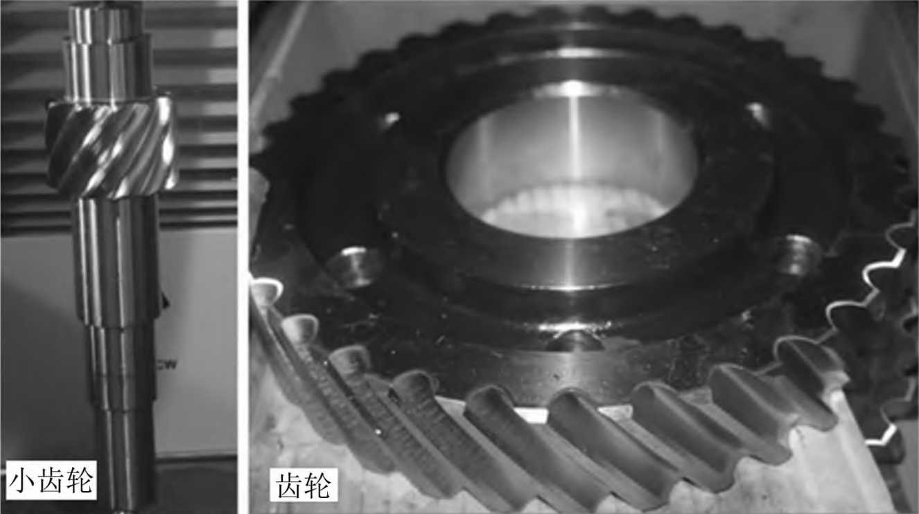
6. Experimental Validation
6.1 Gear Manufacturing
The non-orthogonal helical gears are manufactured using a five-axis milling machine. The tooth profiles are machined according to the designed conjugate curves.
6.2 Performance Testing
The gear pair is tested under varying load and rotational speed conditions. The transmission efficiency is measured using torque sensors and rotational speed encoders. The results confirm the superior performance of non-orthogonal helical gears, with efficiencies exceeding 90% under most operating conditions.
Table 2: Transmission efficiency of non-orthogonal helical gears.
| Rotational Speed (rpm) | Load (Nm) | Transmission Efficiency (%) |
|---|---|---|
| 600 | 300 | 92.5 |
| 800 | 400 | 94.2 |
| 1000 | 500 | 95.9 |
7. Conclusion
This paper presents a comprehensive study on the mathematical modeling and contact characteristics of non-orthogonal helical gears. A novel mathematical model based on curve contact elements is proposed and validated through simulations and experiments. The results indicate that non-orthogonal helical gears exhibit superior contact characteristics, including reduced undercutting, lower slip rates, and more uniform contact stress distributions. These findings suggest that non-orthogonal helical gears have significant potential for high-performance transmission applications.