
Abstract
Logarithmic spiral bevel gear is critical components in mechanical transmission mechanisms. This study utilized SolidWorks software combined with C language programming to establish a parametric gear numerical table and created 3D models of a pair of logarithmic spiral bevel gear based on the size-driven parametric method. The structural rationality of the set gear parameters was verified through meshing assembly and motion analysis of the gears. Additionally, the SolidWorks Simulation module was employed for mesh division, and nonlinear finite element analysis of the solid mesh was conducted. The research focused on exploring the maximum contact stress, contact strength, and contact strain at the meshing area of spiral bevel gear under different torque loads. These findings ensure that the designed spiral bevel gear possess sufficient strength and reliability. Upon verification, the contact strength of the logarithmic spiral bevel gear was found to be below 60.5 N·m within the optimal torque range, with the maximum meshing stress value less than the material’s yield limit. The results provide a reliable reference and method for the structural design and transmission strength of logarithmic spiral bevel gear, offering significant guidance for engineering practices and gear design in related fields.
1. Introduction
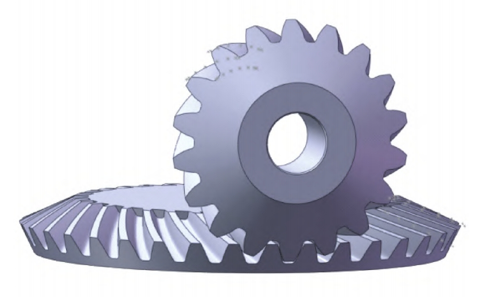
Spiral bevel gear is essential components in mechanical transmissions, renowned for their high load-bearing capacity, efficient power transmission, and smooth motion. They are widely applied in automobiles, engineering machinery, energy, aerospace, and steel rolling machinery. However, during high-speed operation, spiral bevel gear may experience impact and vibration, and the demand for greater load-bearing capacity poses new challenges to the contact length of tooth surfaces. Consequently, logarithmic spiral bevel gear, as a novel gear type, have been introduced to achieve smoother motion transmission and higher load-bearing capacity, making them particularly suitable for high-speed and heavy-duty transmission systems .
In modern engineering design, computer-aided design (CAD) software such as SolidWorks, UG, Pro/E, and MATLAB has significantly facilitated the modeling, analysis, and optimization of spiral bevel gear structures. For instance, Diao Yunlong employed MATLAB to investigate the formation principle of logarithmic spiral bevel gear tooth surfaces and established a tooth surface for conical involute logarithmic spiral bevel gear. Xiang Timing proposed a 3D parametric modeling method for logarithmic spiral bevel gear based on Boolean subtraction operations, implemented using UG/OPEN GRIP secondary development tools. Li Qiang et al. utilized the multi-guideline scan method in Pro/E software to create 3D models of logarithmic spiral bevel gear.
When discrepancies arise between the actual and theoretical parameters of logarithmic spiral bevel gear, deviations in the tooth surface geometry occur, affecting the meshing behavior of the gear pair and, consequently, the overall device performance. Timing Xiang et al. established geometric models of logarithmic spiral bevel gear by sweeping the gear profile along the tooth trace curve, while Xiao Yang et al. conducted analysis and simulation of spiral bevel gear using ANSYS, revealing stress variation patterns and maximum contact stress. Zhang Dawei et al. developed a 3D model of the tooth profile curve for hob cutters based on gear meshing theory and created a special hob model for internal spiral bevel gear using SolidCam.
Previous studies have employed various 3D design and analysis software and methods to model and analyze spiral bevel gear, demonstrating that utilizing advanced software for analyzing logarithmic spiral bevel gear is a reliable and effective approach in engineering. Early methods for evaluating gear contact strength and deformation were mostly tailored to traditional gear manufacturing processes. The prediction of contact strength for near-net-shape logarithmic spiral bevel gear is more complex than for gears processed by traditional tooth cutting techniques.
China is the largest producer of commercial vehicles, manufacturing 12 million to 15 million drive axle spiral bevel gear annually. Due to limitations in manufacturing technology, Chinese industry standards stipulate that spiral bevel gear must undergo full-load bench test cycles of no fewer than 300,000 times, with 10% to 15% of spiral bevel gear damaged due to insufficient contact strength. Therefore, this study employs SolidWorks combined with C language programming to establish parametric models of logarithmic spiral bevel gear, rapidly creating 3D models of spiral bevel gear with corresponding parameters using the size-driven parametric modeling method. The SolidWorks Simulation module is utilized to simulate and analyze the mechanical conditions of a pair of spiral bevel gear under different torques, thereby predicting gear contact strength and assessing maximum stress and prone deformation locations to ensure the contact strength and stiffness of the logarithmic spiral bevel gear studied, providing a reference for practical engineering applications.
2. Structural Design of Logarithmic Spiral Bevel Gear
2.1 Gear Material Properties
The material selected for the logarithmic spiral bevel gear is P91 chromium-molybdenum alloy heat-resistant steel forgings. This material’s primary chemical components include carbon, silicon, manganese, chromium, and molybdenum. P91 alloy exhibits high temperature strength, creep resistance, oxidation resistance, and corrosion resistance, offering higher strength and toughness compared to carbon steel. Specific material property parameters are shown in Table 1.
Table 1. Alloy Steel Material Parameters
| Property | Symbol | Value | Unit |
|---|---|---|---|
| Elastic Modulus | E | 210000 | N/mm² |
| Poisson’s Ratio | ν | 0.28 | – |
| Shear Modulus | G | 79000 | MPa |
| Mass Density | ρ | 7700 | kg/m³ |
| Tensile Strength | σt | 723.8256 | MPa |
| Yield Strength | σs | 620.422 | MPa |
| Thermal Expansion Coefficient | α | 0.0000013 | 1/°C |
2.2 Gear Geometric Structure Parameters
SolidWorks was used as the secondary development platform, combined with C language programming, to establish a program (GearTeq) that automatically completes the parametric modeling of logarithmic spiral bevel gear. The size-driven parametric modeling method enables rapid creation of new gears when basic parameters such as gear modulus, tooth number, and pressure angle are changed. Table 2 presents the parameters used in the GearTeq program for parametric modeling. The “Interface Input” refers to inputting the relevant parameter values through the GearTeq program interface to meet the modeling requirements of logarithmic spiral bevel gear.
Table 2. Parameters for Parametric Modeling of Logarithmic Spiral Bevel Gear
| Parameter Name | Parameter Symbol | Input Type |
|---|---|---|
| Tooth Number | z | Interface Input |
| Large-end Modulus | m | Interface Input |
| Tooth Width | b | Interface Input |
| Addendum Coefficient | hα* | Interface Input |
| Clearance Coefficient | c* | Interface Input |
| Working Tooth Height | hh = m(2hα* + c*) | – |
| Shaft Angle | Σ | 90° |
| Helix Angle | β | Interface Input |
| Pitch Diameter | d1 = m·z·cosδ | – |
| Cone Angle | δ = arctan(z1/z2) | – |
| Outer Diameter | de = d + 2hc·cosδ | – |
| Crown Distance | Xe = Recosδ – hcesinδ | – |
| Addendum Height | ha = m·ha | – |
| Full Tooth Height | hh = m(2ha + c*) | – |
| Dedendum Height | hf = m(1.25 + cotβ) | – |
| Tip Cone Angle | δa = δ + θa | – |
| Root Cone Angle | δf = δ – θf | – |
| Addendum Circle Diameter | da = m·z1·cosγ | – |
| Dedendum Circle Diameter | df = (d – 2·hf·cosδ)·cosδ | – |
| Pressure Angle | α = arctan(tanβ/cosγ) | – |
By setting parameters through the GearTeq program’s input interface, specific geometric parameter values for the spiral bevel gear can be obtained by inputting tooth numbers (z) of 18 and 36 for the pinion and gear, respectively, into the formulas shown in Table 2. These values are presented in Table 3.
Table 3. Geometric Parameters of Logarithmic Spiral Bevel Gear
| Name | Parameter Symbol | Pinion | Gear |
|---|---|---|---|
| Gear Basic Parameters | |||
| Tooth Number | z | 18 | 36 |
| Large-end Modulus | Mt | 2.5 | 2.5 |
| Tooth Width | b | 12.7 | 12.7 |
| Addendum Coefficient | hα* | 1 | 1 |
| Clearance Coefficient | c* | 0.25 | 0.25 |
| Working Tooth Height | hh | 4.38 | 4.38 |
| Shaft Angle | Σ | 90° | 90° |
| Helix Angle | β | 35° | 35° |
| Helix Direction | Right | Left | |
| Geometric Parameter Values | |||
| Pitch Diameter | d | 45 | 90 |
| Cone Angle | δ | 26.565 | 63.3 |
| Crown Distance | Xe | 6.38 | 6.35 |
| Installation Distance | p | 50.772 | 101.544 |
| Addendum Height | ha | 2.9032 | 2.54 |
| Full Tooth Height | hh | 4.7955 | 5.6083 |
| Dedendum Height | hf | 1.8948 | 3.0175 |
| Tip Cone Angle | δa | 30.3475 | 50.3324 |
| Root Cone Angle | δf | 24.4435 | 42.328 |
| Addendum Circle Diameter | da | 42.36 | 84.72 |
| Dedendum Circle Diameter | df | 39.32 | 77.44 |
2.3 Gear Contact Stress
According to the Gear Transmission Design Manual, the contact stress formula for gear tooth surfaces is:
sigmaH=ZEKAKVKHβZRbd12I300Tmax
SH=σHZθσHlimZNTZW
Where:
- σH is the contact stress on the tooth surface.
- Tmax is the maximum working torque.
- b is the tooth width.
- d1 is the pitch diameter of the pinion.
- ZE is the elastic coefficient.
- KA is the service factor.
- KV is the dynamic load factor.
- KHβ is the load distribution factor.
- ZR is the surface condition factor.
- I is the geometric factor for tooth surface contact strength.
- SH is the contact strength safety factor.
- σHlim is the contact fatigue limit.
- ZNT is the contact fatigue strength life coefficient.
- ZW is the work hardening coefficient.
- Zθ is the temperature coefficient.
The parameter values used in this study for logarithmic spiral bevel gear is shown in Table 4.
Table 4. Contact Stress Parameter Values for Logarithmic Spiral Bevel Gear
| Parameter Meaning | Parameter Value | Parameter Meaning | Parameter Value |
|---|---|---|---|
| Elastic Coefficient | ZE = 189.8 | Stress Cycle Coefficient | ZNT = 1.97 |
| Overload Coefficient | KA = 1.0 | Hardness Ratio Coefficient | ZW = 1.0 |
| Dynamic Load Coefficient | KV = 1.0 | Tooth Surface Contact Strength Geometric Factor | I = 1.23 |
| Load Distribution Coefficient | KHβ = 1.8 | Size Coefficient | ZX = 4.1 |
| Temperature Coefficient | Zθ = 0.85 | Surface Condition Coefficient | ZR = 0.85 |
Assuming a minimum safety factor of 1.25 ensures that the gear will not fail, achieving the safest state. If the input power ((P)) and rotational speed ((n)) of the pinion are known, the torque ((T)) can be calculated using the relationship:
T=n9549×P
2.4 Structural Design of Logarithmic Spiral Bevel Gear
Based on the size-driven parametric modeling method and the given values (Table 3), digital models of the logarithmic spiral bevel gear were established using SolidWorks software. To assess their strength and rationality, strength verification was performed using the theoretical contact stress formulas (1) and (2). Meshing fit and motion analysis were conducted on the pinion and gear to verify the structural rationality of the designed spiral bevel gear.
3. Finite Element Model Establishment and Mechanical Analysis
3.1 Finite Element Model Mesh Division
In the SolidWorks Simulation module, the fineness of mesh division affects both the speed of simulation calculations and the accuracy of analysis results. For the overall mesh division of the logarithmic spiral bevel gear in this study, a larger mesh size was used, with finer mesh division applied to the gear meshing area to enhance the mesh division precision and analysis accuracy. The mesh type used was solid, with mesh quality set to high and mesh element size set to 1.5 mm. A total of 158,106 elements and 234,797 nodes were divided.
3.2 Static Stress Analysis
In the static stress analysis, the rotational degree of freedom around the axis of the driving pinion gear was retained, while other degrees of freedom were constrained, and torque loads were applied. The driven gear was fully constrained. Torques of 50, 100, 150, and 200 N·m were applied to the driving pinion gear, and the friction coefficient was set to 0.1 for stress analysis.
It can be observed that when torques of 50, 100, 150, and 200 N·m are applied to the gears, the maximum stresses obtained are 469.6, 644.2, 1227, and 4704 MPa, respectively. Maximum stresses are concentrated mainly in the gear meshing area, tooth roots, and tooth tips, where deformation and damage are more likely to occur.
3.3 Contact Stress Analysis
To study the contact strength of logarithmic spiral bevel gear, special attention was paid to the analysis of contact stress on gear tooth surfaces. Therefore, the probe command in SolidWorks was used to measure the stress in the meshing area.
The maximum, minimum, and average stresses under different torques are presented in Table 5. When the applied torque causes the maximum stress on a part to exceed the yield stress, plastic deformation or even fracture may occur. In such cases, redesigning the part structure or selecting a suitable material is necessary to ensure system safety and reliability.
the maximum, minimum, and average stresses recorded at various torque levels applied to the logarithmic spiral bevel gear. This data provides crucial insights into the stress distribution and the potential for material failure under different loading conditions.
When the maximum stress exceeds the yield stress of the material, it signifies that the material has reached its elastic limit and is on the verge of undergoing plastic deformation. Plastic deformation is permanent and irreversible, which can lead to significant loss of structural integrity and potentially catastrophic failure if not addressed promptly.
In the context of the study, when the applied torque increases, the maximum stress on the gear teeth also rises. For instance, at a torque of 100 N·m, the maximum stress of 644.2 MPa slightly surpasses the yield strength of 620.422 MPa for the P91 chromium-molybdenum alloy steel used in the gears. This indicates that the gears may experience minor deformation under this load. However, at higher torques of 150 N·m and 200 N·m, the maximum stresses soar to 1227 MPa and 4704 MPa, respectively, far exceeding the material’s yield limit. This scenario presents a high risk of severe deformation or even fracture of the gears.
To mitigate these risks and ensure the safe and reliable operation of the gear system, several corrective measures can be taken:
- Redesigning the Gear Structure: By modifying the gear geometry, such as increasing the tooth thickness or optimizing the tooth profile, the stress distribution can be altered to reduce peak stresses.
- Selecting a Suitable Material: Choosing a material with a higher yield strength and better ductility can enhance the gear’s resistance to deformation and fracture.
- Applying Load Management Techniques: Implementing strategies to distribute the load more evenly across the gear teeth or reducing the maximum torque levels can help keep stresses within safe limits.
- Performing Advanced Simulations and Testing: Conducting more sophisticated finite element analysis (FEA) and physical testing can provide deeper insights into the gear’s behavior under various conditions, guiding further design refinements.
In summary, the data presented in Table 5 underscores the importance of carefully considering stress levels and material properties in gear design. By addressing potential stress exceedances through redesign, material selection, or load management, the safety and reliability of the logarithmic spiral bevel gear system can be significantly enhanced.