1. Introduction
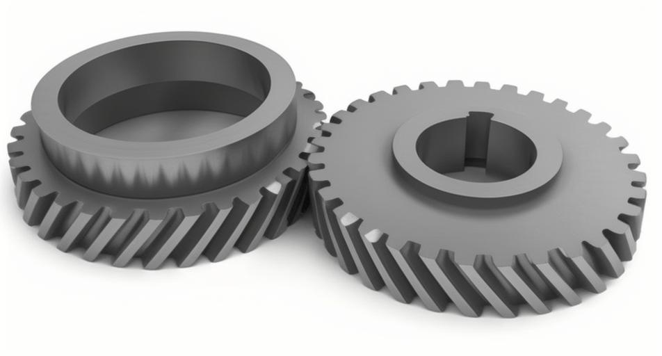
Helical gears play a critical role in various transmission systems due to their efficiency, smooth operation, and noise reduction. In Electric Power Steering (EPS) systems, helical gears combined with worm transmissions are frequently used, especially where nylon helical gears mate with steel worm gears. This configuration allows for improved transmission stability, reduced noise, and cost-effectiveness. However, designing helical gears for such systems requires addressing unique challenges, such as material compatibility, stress optimization, and efficient load distribution.
This article provides a comprehensive study on the design and optimization of helical gears within EPS worm transmission systems, focusing on performance, cost, and structural considerations. Numerous tables and formulas will summarize the key findings, and graphical illustrations will accompany the analysis.
2. Basic Concepts of Helical Gears
Helical gears differ from spur gears in that their teeth are cut at an angle to the face of the gear, resulting in smoother and quieter operation due to increased contact between the teeth over a longer period. Key design parameters include the helix angle, module, pressure angle, and gear ratio.
| Parameter | Description | Impact on Performance |
|---|---|---|
| Helix Angle (β) | Angle at which gear teeth are cut | Increases load-carrying capacity |
| Module (mn) | Size of the gear teeth | Determines the overall size of the gear |
| Pressure Angle (α) | Angle of the gear teeth contact with the worm | Affects the gear’s strength and meshing efficiency |
| Gear Ratio | Ratio of worm to helical gear turns | Impacts the overall speed and torque transmitted |
3. Analysis of Helical Gears in EPS Systems
In EPS systems, noise and efficiency are key factors. A nylon-steel combination is often used due to the material properties of nylon, which provide good damping properties, while steel offers high strength and durability.
3.1 Material Considerations
| Material | Elastic Modulus (GPa) | Density (kg/m³) | Yield Strength (MPa) |
|---|---|---|---|
| Nylon (PA66) | 1.4 | 1140 | 83 |
| Steel (40Cr) | 21.17 | 7850 | 785 |
Using these materials allows for lightweight, cost-effective gear design while maintaining high strength for the steel worm. One challenge is the difference in thermal expansion, which must be accounted for in the design.
4. Gear Design and Optimization Using Kisssoft
Kisssoft is commonly used for gear design, enabling engineers to input critical parameters and simulate various configurations. In this analysis, a nylon helical gears and steel worm gear were designed and simulated.
4.1 Initial Design Parameters
| Parameter | Helical Gear | Worm Gear |
|---|---|---|
| Module (mn) | 2 mm | 2 mm |
| Helix Angle (β) | 13.5° | – |
| Center Distance | 50 mm | 50 mm |
| Number of Teeth | 41 | 2 |
| Power Input | – | 0.3 kW |
| Speed (n) | – | 1000 RPM |
These design parameters were used as input to Kisssoft to calculate the overall transmission efficiency, safety factors, and stress distribution.
5. Stress and Safety Factor Analysis
Using finite element methods (FEM) in tools like Ansys Workbench, the helical gear’s safety factors were calculated under various load conditions. Below are the results of the stress analysis:
| Parameter | Without Profile Shift (x=0) | With Profile Shift (x=1.3086) | With Profile Shift (x=1.4383) |
|---|---|---|---|
| Max Stress (MPa) | 62.24 | 41.12 | 38.17 |
| Safety Factor | 1.60 | 2.018 | 2.174 |
6. Optimization of Profile Shift Coefficient
A key design decision in helical gears involves adjusting the profile shift coefficient. A higher shift coefficient can strengthen the gear teeth, improving load distribution and reducing stress.
6.1 Profile Shift Calculation
The formulas for profile shift in helical gears are derived from gear theory. Below is the general formula used to calculate the tooth thickness with profile shift:s=π⋅mn+2x⋅mn⋅tanαs = \pi \cdot mn + 2x \cdot mn \cdot \tan \alphas=π⋅mn+2x⋅mn⋅tanα
Where:
- sss is the tooth thickness,
- mnmnmn is the module,
- xxx is the profile shift coefficient,
- α\alphaα is the pressure angle.
For worms, the tooth thickness formula is similarly derived, ensuring compatibility between the worm and gear:sworm=π⋅mn−2x⋅mn⋅tanαs_{worm} = \pi \cdot mn – 2x \cdot mn \cdot \tan \alphasworm=π⋅mn−2x⋅mn⋅tanα
7. Simulation Results
The optimized design was validated using simulation tools such as Ansys Workbench. The stress analysis indicated that with profile shift, the maximum stress in the nylon gear decreased significantly, leading to improved performance and increased safety factors.
7.1 Stress Distribution Analysis
Below is a stress nephogram showing the stress distribution in the helical gears tooth root under different profile shifts:
| Profile Shift | Max Stress (MPa) | Location |
|---|---|---|
| No Shift (x=0) | 62.24 | Tooth root |
| Shift (x=1.3086) | 41.12 | Tooth root |
| Shift (x=1.4383) | 38.17 | Tooth root |
8. Conclusion
This analysis of helical gears in EPS worm transmissions demonstrates that careful design optimization, including the selection of materials and the adjustment of profile shift coefficients, can significantly improve gear performance. With the aid of software like Kisssoft and Ansys Workbench, these designs can be efficiently modeled and validated. Helical gears provide an excellent solution in automotive applications where noise reduction, efficiency, and smooth operation are essential.
Key Takeaways:
- Nylon-steel gear combinations are effective for lightweight, durable, and quiet transmissions.
- Profile shift optimization can reduce gear stress and improve safety factors.
- Simulation tools are invaluable in validating complex gear designs.
